Eureka AIR delivers breakthrough ideas for toughest innovation challenges, trusted by R&D personnel around the world.

Position determination in a high-pressure chamber

Active Publication Date: 2022-09-06
SIEMENS AG
View PDF13 Cites 0 Cited by
  • Summary
  • Abstract
  • Description
  • Claims
  • Application Information

AI Technical Summary

Benefits of technology

The apparatus described in this patent allows for precise measurement of an object's position in a high pressure chamber. It uses a flexible region that is not significantly affected by changes in the chamber's pressure or temperature. The apparatus also minimizes the transmission of vibrations and allows for easy mounting and dismounting of sensors without the need for additional openings. A tension spring or pressure spring can be used to compensate for thermal deformation, and the flexible region can be designed as a tube spiral or a section in a guiding tube. The sensor is secured by a spring-loaded carrier tube or a sealing material. These features make the apparatus more robust and reliable for use in high pressure chambers.

Problems solved by technology

This differential pressure can damage the insulation of the flexible cable.

Method used


Image

  • Position determination in a high-pressure chamber
  • Position determination in a high-pressure chamber
  • Position determination in a high-pressure chamber

Examples


Embodiment Construction

[0031]Parts that correspond to one another are provided with identical reference numerals in the figures.

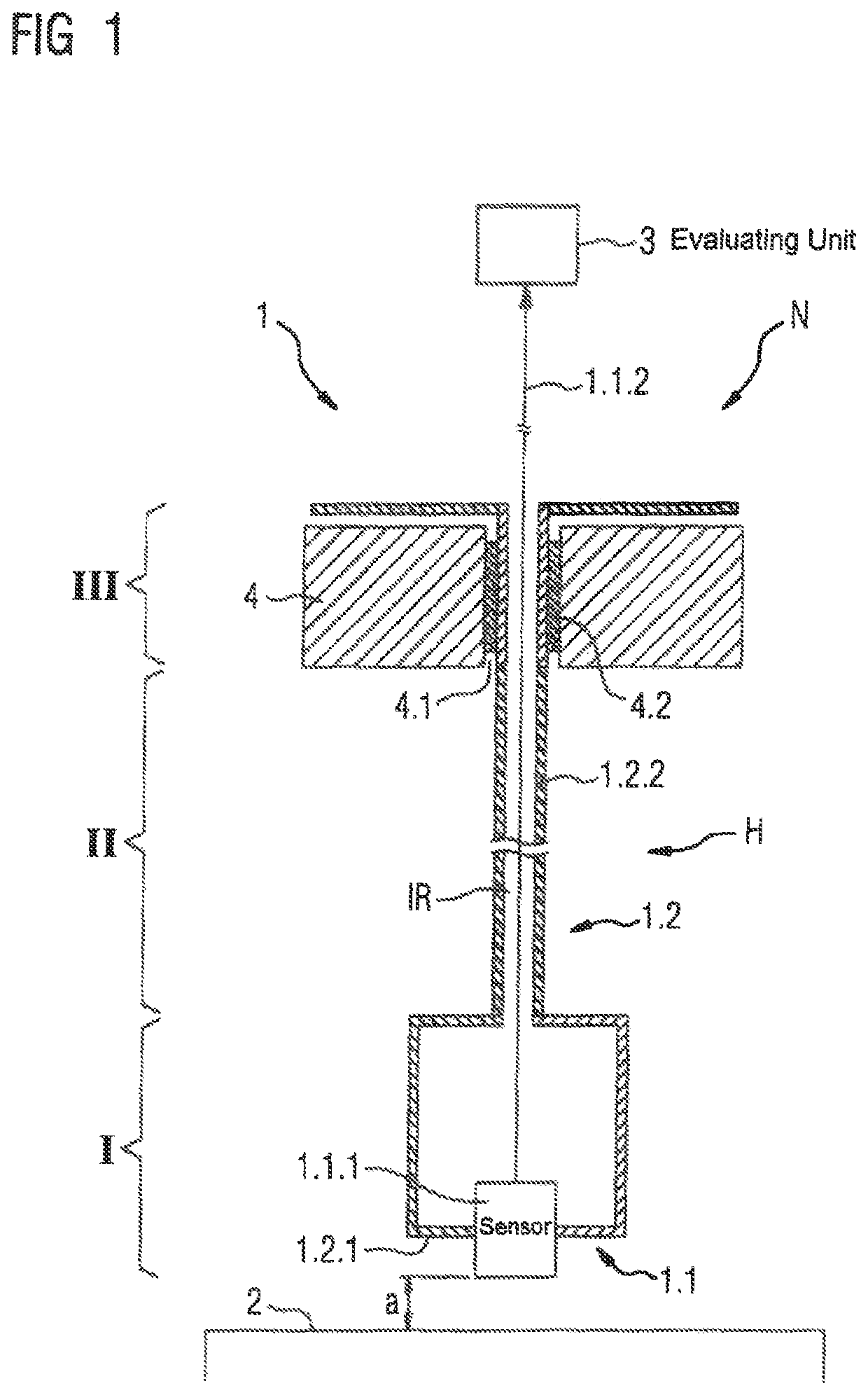
[0032]FIG. 1 illustrates a sectional view of an apparatus 1 for determining a position of a movable object 2 in a high pressure chamber H.

[0033]The apparatus 1 is used in particular to determine an absolute position of the object 2 in a high pressure gas atmosphere. The object 2 is for example a rotatable shaft that is magnetically mounted and that is a component of a gas-cooled electric motor or generator. It is also feasible that the object 2 is a component of a machine that is exposed to aggressive gases, fluids or particle flows in the high pressure chamber H. The determination of the position of the object 2 in the high pressure chamber H is used for an optimal operation of the electric motor / generator or the machine and also other components and / or functions that are coupled to said machine.

[0034]The apparatus 1 that is illustrated in FIG. 1 comprises a detecting unit 1.1 a...


PUM


Abstract

Apparatus for determining a position of a movable object in a high pressure chamber includes a housing configured to delimit the high-pressure chamber and a carrier unit having an object-facing stationary end and a flexible region arranged between the stationary end and a region that extends through the housing. The flexible region is formed by a section of a guiding tube in the form of a tube spiral. A detecting unit is received in the carrier unit and includes a sensor for detecting a position of the object and outputting a position signal, and a sensor cable guided out of the high pressure chamber through the guiding tube and through the region for relaying the position signal to an evaluating unit. The sensor is arranged stationary in the high pressure chamber on the stationary end of the carrier unit.

Description

CROSS-REFERENCES TO RELATED APPLICATIONS[0001]This application is the U.S. National Stage of International Application No. PCT / EP2020 / 054039, filed Feb. 17, 2020, which designated the United States and has been published as international Publication No. WO 2020 / 200564 A1 and which claims the priorty of European Patent Application, Serial No. 19166193.3, filed Mar. 29, 2019, pursuant to 35 U.S.C. 119(a)-(d).BACKGROUND OF THE INVENTION[0002]The invention relates to an apparatus for determining a position of a movable object in a high pressure chamber. The invention furthermore relates to a use of the apparatus,[0003]Apparatuses of this type are known from the prior art. For example, sensors having flexible electrical cables are used to determine the position of gas-cooled electric motors. The flexible cables consist for example of an arrangement of multiple to many thin wires that are twisted together (also referred to as stranded wire). The stranded wire is surrounded by an insulator...

Claims


Application Information

Patent Timeline
IPC IPC(8): H02K11/21G01D5/14
CPCH02K11/21G01D5/14G01D11/24G01D11/30
Inventor BURGHARD, MATTHIAS JOHANNESDENK, JOACHIMFESTA
Owner SIEMENS AG
Why Eureka
Eureka Blog
Learn More