
Porous electrode for electrochemical cells

a technology of electrochemical cells and porous electrodes, applied in the field of electrochemical cells, can solve the problems of low conductivity of solid polymer electrolyte, cycle life and safety problems, and the dilemma of balancing high conductivity and high modulus needs

Active Publication Date: 2022-09-20
LIBAMA POWER CORP
View PDF13 Cites 0 Cited by
  • Summary
  • Abstract
  • Description
  • Claims
  • Application Information

AI Technical Summary

Benefits of technology

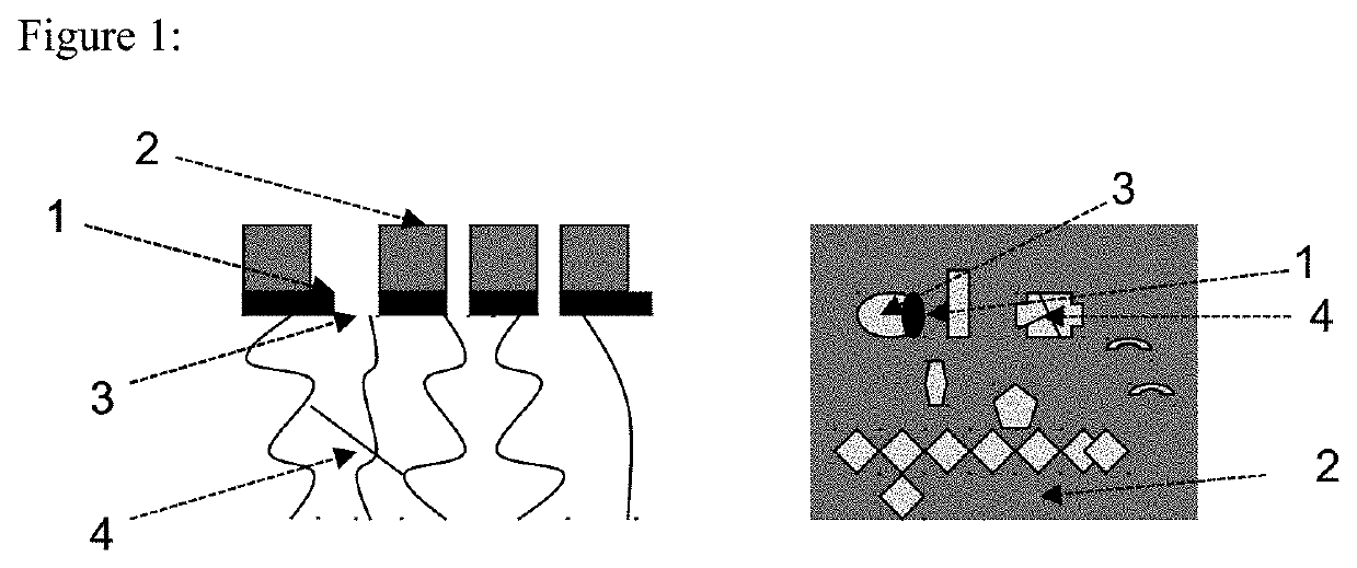
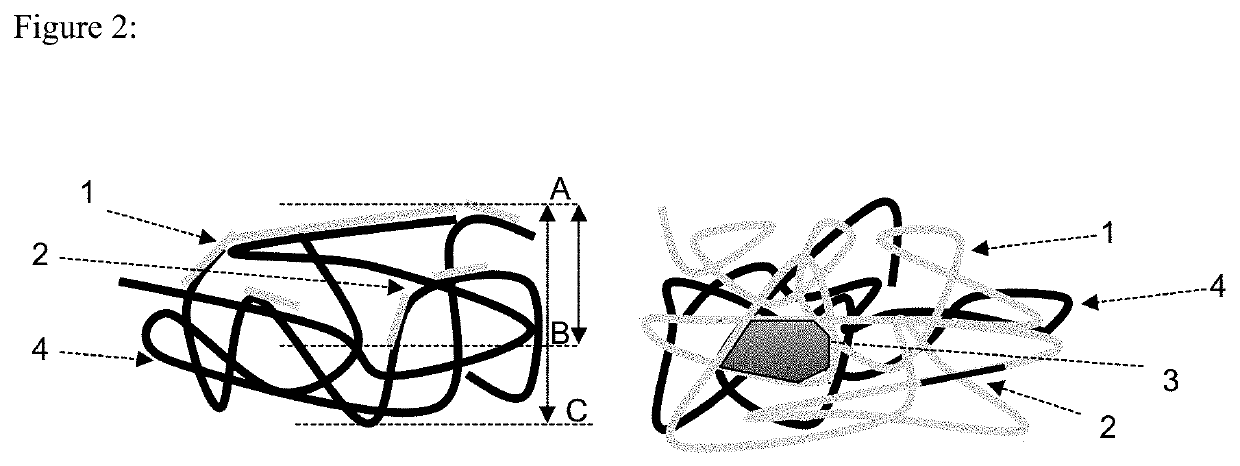
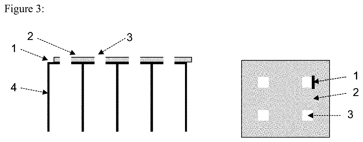
The present invention provides an electrode for an electrochemical cell that has a porous conductive layer and an insulating layer. The porous conductive layer is made of a porous material that can incorporate active metal, while the insulating layer is made of non-conductive materials. The electrode can be formed using various methods, such as physical vapor deposition, chemical vapor deposition, electrostatic spray deposition, mechanical forming, or printing methods. The insulating layer can cover the conductive layer and the uncovered top surface area of the conductive layer is preferably no more than 50% of the available top surface area. The electrode can be used as an anode or part of an anode in an electrochemical cell. The invention also provides a method for making the electrode. The technical effects of the invention include improved performance and efficiency of the electrode in an electrochemical cell, reduced pore size, and increased pore volume.

Problems solved by technology

However, electrochemical cells with metal anodes, such as rechargeable lithium metal batteries, have cycle life and safety problems associated with dendrite formation during the charging process.
However, solid polymer electrolyte has low conductivity, which is typically in the range of 10−6 to 10−4 S / cm at room temperature.
So there is a dilemma for balancing the high conductivity need and high modulus need.

Method used


Image

  • Porous electrode for electrochemical cells
  • Porous electrode for electrochemical cells
  • Porous electrode for electrochemical cells

Examples


examples

[0050]Several embodiments of the present invention are described in the following examples, which are offered by way of illustration and not by way of limitation.

[0051]Example 1: In one embodiment, a thin copper foil is first press fixed onto a platinum foil face to face and then attached to the working terminal of a potentiostat / galvanostat. The foils are then immersed into a CuSO4 / H2SO4 aqueous solution. After setting up the platinum counter electrode and Ag / AgCl reference electrode, positive current pulse is applied to the copper foil to randomly strip copper and thus a porous copper foil is obtained. The perforated copper foil is then separated from the platinum foil and one side protected with a Scotch tape and attached again to the working terminal of the potentiostat / galvanostat. Negative current pulse is then applied to the copper foil and random copper is grown onto the perforated copper foil. Thus a porous conductive layer made of copper is obtained. The porous copper foil...


PUM

PropertyMeasurementUnit
electrical conductivityaaaaaaaaaa
electronic conductivityaaaaaaaaaa
thicknessaaaaaaaaaa

Abstract

A porous electrode for electrochemical cells, methods of making the same and its application are described. The porous electrode is comprised of a porous conductive layer and an insulating layer, whereas the pores inside the conductive layer function as mini-containers for the active metal for rechargeable batteries, and the insulating material covers the top conductive surface of the conductive layer and blocks the sites where active metal dendrite would otherwise preferentially grow. An example of such electrodes is a porous copper foil with top surface coated with polyvinylene difluoride (PVDF). Electrochemical cells containing the invented electrode, such as rechargeable lithium batteries, sodium batteries and aluminum batteries, have good cycle life and safety performance.

Description

CROSS-REFERENCE TO RELATED APPLICATIONS[0001]This patent application claims a priority date of Sep. 30, 2016 for U.S. provisional patent application 62 / 402,932 filed on Sep. 30, 2016.TECHNICAL FIELD[0002]The present application relates generally to the field of electrochemical cells where a metal anode is used or formed, such as rechargeable lithium metal batteries, rechargeable sodium batteries, lithium air batteries, zinc air batteries, and aluminum air batteries. More particularly, this application relates to a conductive porous electrode that has insulating surfaces. The present application also relates to methods of forming such electrodes, electrochemical cells comprising such electrodes, and methods of making such electrochemical cells.BACKGROUND[0003]With the broader adoption of portable electronic devices and electrified vehicles, there have been considerable need and interest for electrochemical energy storage devices that have higher energy density than state-of-the-art l...

Claims


Application Information

Patent Timeline
Patent Type & Authority Patents(United States)
IPC IPC(8): H01M4/04H01M4/38H01M10/00H01M4/62H01M50/116H01M4/02
CPCH01M10/00H01M4/0402H01M4/381H01M4/382H01M4/62H01M4/624H01M50/116H01M2004/027H01M4/661H01M4/664H01M4/667H01M4/38H01M4/668H01M4/134H01M4/663Y02E60/10
Inventor LI, WENTAO
Owner LIBAMA POWER CORP
Learn More