Magnetic tape having characterized magnetic layer, magnetic tape cartridge, and magnetic tape apparatus

a technology of magnetic layer and magnetic tape, which is applied in the direction of magnetic materials for record carriers, instruments, record information storage, etc., can solve the problems of increasing the distance between the surface of the magnetic layer and the reproducing element of the head, affecting the performance of the magnetic layer, etc., and achieves the effect of deteriorating the electromagnetic conversion characteristics

Active Publication Date: 2022-10-11
FUJIFILM CORP
View PDF529 Cites 0 Cited by
  • Summary
  • Abstract
  • Description
  • Claims
  • Application Information

AI Technical Summary

Benefits of technology

[0006]Meanwhile, the magnetic tape is normally used to be accommodated and circulated in a magnetic tape cartridge. In order to increase recording capacity for one reel of the magnetic tape cartridge, it is desired to increase a total length of the magnetic tape accommodated in one reel of the magnetic tape cartridge. In order to increase the total length of the magnetic tape, it is necessary that the magnetic tape is thinned (hereinafter, referred to as “thinning”). As a method for thinning the magnetic tape, a method of decreasing a total thickness of a non-magnetic layer and a magnetic layer of a magnetic tape including the non-magnetic layer and the magnetic layer on a non-magnetic support in this order is used. However, the inventors have conducted studies and found that, in a magnetic tape in which a total thickness of a non-magnetic layer and a magnetic layer is decreased to be equal to or smaller than 0.60 μm, a deterioration in electromagnetic conversion characteristics during the repeated reproducing easily occurs in a low temperature and high humidity environment, compared to a magnetic tape in which a total thickness of a non-magnetic layer and a magnetic layer is greater than 0.60 μm. In order to use a magnetic tape in a low temperature and high humidity environment, it is desired to prevent a deterioration in electromagnetic conversion characteristics during the repeated reproducing in such an environment.
[0017]According to one aspect of the invention, it is possible to provide a magnetic tape having a total thickness of a non-magnetic layer and a magnetic layer of equal to or smaller than 0.60 μm, in which a deterioration in electromagnetic conversion characteristics during the repeated reproducing in a low temperature and high humidity environment can be prevented. In addition, according to the other aspect of the invention, it is possible to provide a magnetic tape cartridge and a magnetic tape apparatus including the magnetic tape.

Problems solved by technology

However, in a case where chipping of a surface of a magnetic layer and / or a head occurs, during the sliding between the surface of the magnetic layer and the head is repeated, a phenomenon in that a distance between the surface of the magnetic layer and a reproducing element of the head increases (so-called spacing loss) may occur.
On the other hand, as the head cleaning properties of the surface of the magnetic layer is increased, the chipping of the head easily occurs due to the sliding on the surface of the magnetic layer, and the spacing loss may occur.

Method used


Image

  • Magnetic tape having characterized magnetic layer, magnetic tape cartridge, and magnetic tape apparatus

Examples


example 1

[0123](1) Preparation of Alumina Dispersion

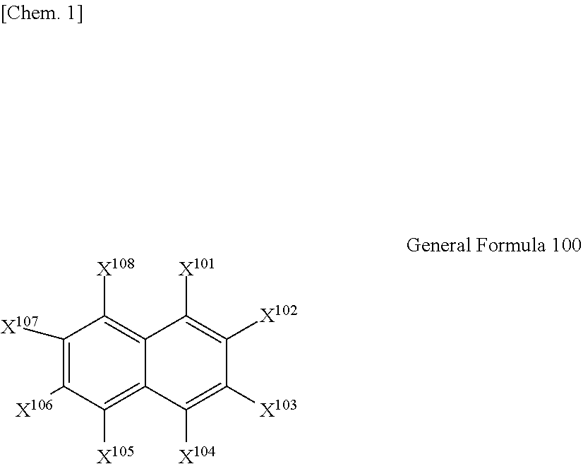
[0124]The amount of 2,3-dihydroxynaphthalene (manufactured by Tokyo Chemical Industry Co., Ltd.) shown in Table 1, 31.3 parts of a 32% solution (solvent is a mixed solvent of methyl ethyl ketone and toluene) of a polyester polyurethane resin including a SO3Na group as a polar group (UR-4800 (polar group amount: 80 meq / g) manufactured by Toyobo Co., Ltd.), and 570.0 parts of a mixed solvent of methyl ethyl ketone and cyclohexanone (mass ratio of 1:1) as a solvent were mixed with 100.0 parts of oxide abrasive (alumina powder) shown in Table 1, and dispersed in the presence of zirconia beads (bead diameter: 0.1 mm) by a paint shaker for a period of time shown in Table 1 (bead dispersion time). After the dispersion, the centrifugal separation process of a dispersion liquid obtained by separating the dispersion liquid from the beads by mesh was performed. The centrifugal separation process was performed by using CS150GXL manufactured by Hitachi,...

examples 2 to 6

, Comparative Examples 1 to 7, and Reference Examples 1 and 2

[0147]A magnetic tape was manufactured by the same method as in Example, except that various conditions were changed as shown in Table 1.

[0148]In Table 1, in Examples 2 to 6 and Comparative Examples 3 and 5 in which “performed” is shown in the column of the alternating magnetic field application during coating and the column of the burnishing process, the step subsequent to the coating step of the magnetic layer forming composition was performed by the same method as in Example 1. That is, the application of the alternating magnetic field was performed during coating of the magnetic layer forming composition in the same manner as in Example 1, and the burnishing process and the wiping process were performed with respect to the magnetic layer.

[0149]With respect to this, in Comparative Example 7 in which “not performed” is shown in the column of the burnishing process, the step subsequent to the coating step of the magnetic ...


PUM

PropertyMeasurementUnit
total thicknessaaaaaaaaaa
particle diameteraaaaaaaaaa
total thicknessaaaaaaaaaa

Abstract

The magnetic tape includes a non-magnetic support; a non-magnetic layer including a non-magnetic powder and a binding agent on the non-magnetic support; and a magnetic layer including a ferromagnetic powder and a binding agent on the non-magnetic layer, in which a total thickness of the non-magnetic layer and the magnetic layer is equal to or smaller than 0.60 μm, an isoelectric point of a surface zeta potential of the magnetic layer is equal to or greater than 5.5, the magnetic layer includes an oxide abrasive, and an average particle diameter of the oxide abrasive obtained from a secondary ion image obtained by irradiating the surface of the magnetic layer with a focused ion beam is 0.04 μm to 0.08 μm.

Description

CROSS-REFERENCE TO RELATED APPLICATIONS[0001]This application claims priority under 35 U.S.C 119 to Japanese Patent Application No. 2018-198191 filed on Oct. 22, 2018. The above application is hereby expressly incorporated by reference, in its entirety, into the present application.BACKGROUND OF THE INVENTION1. Field of the Invention[0002]The present invention relates to a magnetic tape, a magnetic tape cartridge, and a magnetic tape apparatus.2. Description of the Related Art[0003]Magnetic recording media are divided into tape-shaped magnetic recording media and disk-shaped magnetic recording media, and tape-shaped magnetic recording media, that is, magnetic tapes are mainly used for data storage such as data back-up.[0004]The recording of information on a magnetic tape and / or reproducing of the information on the magnetic tape is normally performed by setting a magnetic tape cartridge in which the magnetic tape is accommodated, in a drive, and causing the magnetic tape to run in t...

Claims


Application Information

Patent Timeline
Patent Type & Authority Patents(United States)
IPC IPC(8): G11B5/708G11B5/71G11B5/706G11B5/702G11B5/735G11B5/78G11B23/04
CPCG11B5/7085G11B5/702G11B5/706G11B5/7021G11B5/71G11B5/7356G11B5/78G11B23/041G11B5/7006G11B5/8408G11B5/70
Inventor IWAMOTO, TAKAHIROKASADA, NORIHITO
Owner FUJIFILM CORP
Why Eureka
Try Eureka