Planetary gearbox assembly for a turbine engine

a turbine engine and gearbox technology, applied in the direction of gearing details, machines/engines, efficient propulsion technologies, etc., can solve problems such as damage to elastic members

Active Publication Date: 2022-11-15
SAFRAN TRANSMISSION SYST
View PDF11 Cites 0 Cited by
  • Summary
  • Abstract
  • Description
  • Claims
  • Application Information

AI Technical Summary

Benefits of technology

[0020]In the present invention, the planetary carrier is connected to the stator element by a flexible connection comprising an elastic member. This elastic member can be designed to confer a flexibility in the axial, radial and torsion direction to the connection. This flexible connection also ensures transmission of the forces between the planetary carrier and the stator element. Beyond a certain torsion force threshold and therefore torque about the axis X, the elastic member is likely to be broken. To avoid this, the planetary carrier comprises teeth which are capable of engaging by abutment in the circumferential direction with the stator element. These teeth are thus intended to take over the transmission of the forces in the abovementioned case, where the torsion forces transmitted by the planetary carrier would be too much and would be likely to damage the elastic member. The teeth are advantageously free to be moved radially and axially with respect to the stator element.
[0021]The absorption systems make it possible to absorb the vibrations to which the operating planetary carrier is subjected.
[0025]the teeth and the fingers are at least partially formed of unitary construction with the body; this makes it possible to simplify the production and the assembly of the cage carrier,
[0031]said planetary carrier comprises tapped orifices for screwing fixing screws of said first flange to the planetary carrier; the planetary carrier does not thus comprise any dedicated flange for fixing to the member which is, on the contrary, directly fixed on the planetary carrier, which reduces the volume of the assembly,
[0032]said teeth and said tapped orifices are substantially located in the same plane P1 perpendicular to said axis X; this can also make it possible to optimise the volume of the assembly,
[0038]said arms comprise leading edges located in a plane P2 perpendicular to said axis X and trailing edges located in a plane P3 perpendicular to said axis X, the housings and the fingers being located in a plane P1 located between the planes P2 and P3; this can make it possible to optimise the volume of the module.

Problems solved by technology

These teeth are thus intended to take over the transmission of the forces in the abovementioned case, where the torsion forces transmitted by the planetary carrier would be too much and would be likely to damage the elastic member.

Method used


Image

  • Planetary gearbox assembly for a turbine engine
  • Planetary gearbox assembly for a turbine engine
  • Planetary gearbox assembly for a turbine engine

Examples


Embodiment Construction

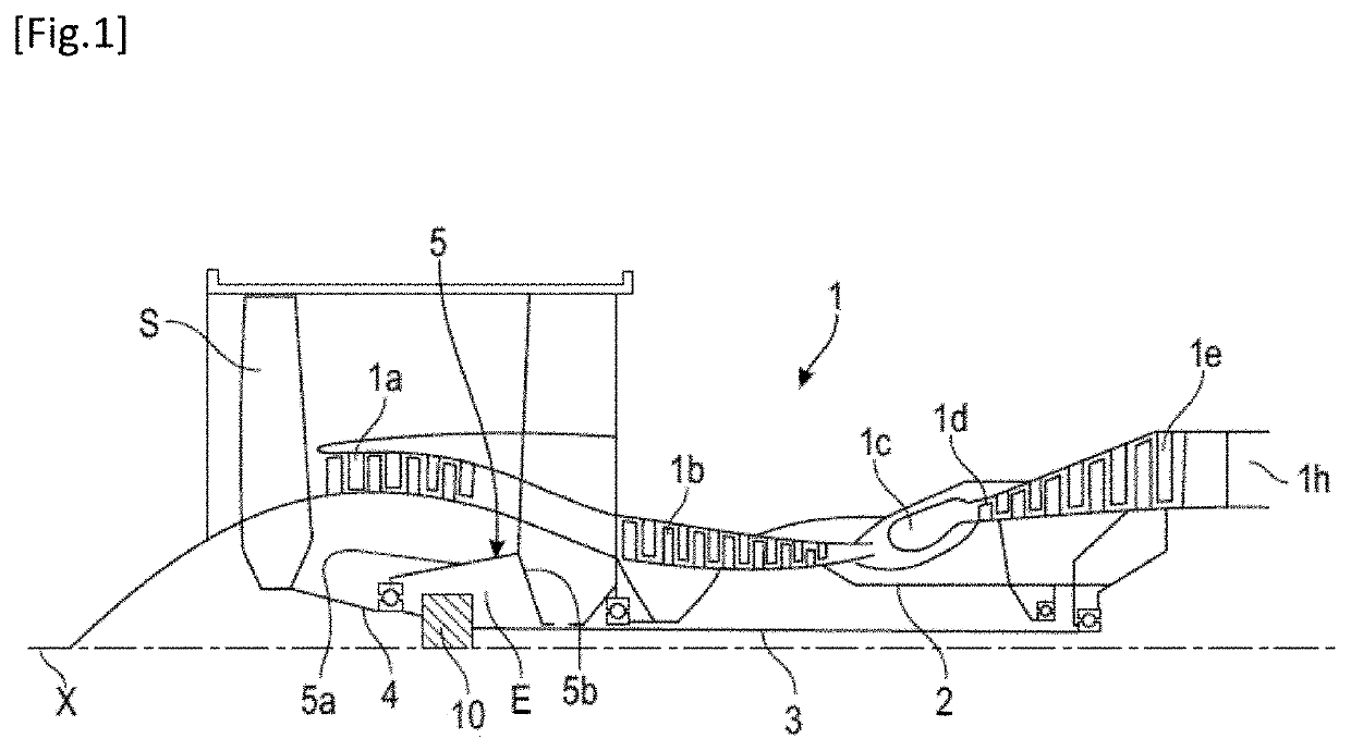
[0054]FIG. 1 describes a turbine engine 1 which comprises, conventionally, a fan S, a low-pressure compressor 1a, a high-pressure compressor 1b, an annular combustion chamber 1c, a high-pressure turbine 1d, a low-pressure turbine 1e and an exhaust pipe 1h. The high-pressure compressor 1b and the high-pressure turbine 1d are connected by a high-pressure shaft 2 and form with it a high-pressure (HP) body. The low-pressure compressor 1a and the low-pressure turbine 1e are connected by a low-pressure shaft 3 and form with it a low-pressure (LP) body.

[0055]The fan S is driven by a fan shaft 4 which is connected to the LP shaft 3 by means of a reduction gear 10. This reduction gear is generally of the planetary or epicyclic type.

[0056]Although the following description relates to a reduction gear of the planetary or epicyclic type, it also applies to a mechanical differential, in which the three main components thereof, which are the planetary carrier, the ring gear and the sun gear, are ...


PUM


Abstract

A planetary gear train speed reduction gear planetary carrier (130) assembly and an elastically deformable annular member (160), for a turbine engine, in particular for an aircraft. The planetary carrier (130) has a general annular shape about an axis X. The annular member (160) extends about the axis X, and is fixed to the planetary carrier and configured to be fixed to a stator element (162) of the turbine engine ensuring a flexible connection between the planetary carrier and the stator element. The planetary carrier carries a series of protruding teeth (180) extending substantially radially outwards with respect to the axis X. Each of these teeth has first opposite side faces (180a, 180b) extending into planes passing through the axis X capable of engaging by abutment in the circumferential direction with the stator element. A vibration absorption system is inserted between the first faces and the stator element.

Description

TECHNICAL FIELD OF THE INVENTION[0001]The present invention relates to the field of planetary gear train speed reduction gears for turbine engines, in particular, of aircraft.TECHNICAL BACKGROUND[0002]The state of the art comprises, in particular, documents WO-A1-2010 / 092263, FR-A1-2 987 416, EP-A1-1 464 869, FR-A1-3 041 054 FR-A1-2 853 382, FR-A1-3 052 213, JP-A-2009 058002, US-A1-2013 / 023378 and US-A1-2011 / 252907.[0003]The role of a mechanical reduction gear is to modify the speed and torque ratio between the input axis and the output axis of a mechanism.[0004]New generations of bypass turbine engines, in particular those having a high dilution rate, comprise a mechanical reduction gear to drive the shaft of a fan. Usually, the reduction gear aims to transform the rotation speed, termed rapid rotation speed, of the shaft of a power turbine into a slower rotation speed for the shaft driving the fan.[0005]Such a reduction gear comprises a central pinion, termed sun gear, a ring gear...

Claims


Application Information

Patent Timeline
Patent Type & Authority Patents(United States)
IPC IPC(8): F02C7/36F01D25/04F02C7/06
CPCF02C7/36F01D25/04F02C7/06F05D2220/323F05D2240/10F16H57/023F16H57/028F16H57/082F16H2057/02039F16H57/0006F16H57/0424F16H57/043F16H57/0431F16H57/0479F16H57/0482F05D2260/96F05D2260/40311F05D2260/98Y02T50/60
Inventor SIMON, ADRIEN LOUISLEFEBVRE, SIMON LOIC CLEMENT
Owner SAFRAN TRANSMISSION SYST
Why Eureka
Try Eureka