

Compressed mesh wick, method for manufacturing same, and plate type heat pipe including compressed mesh wick
a technology of mesh wick and heat pipe, which is applied in the direction of cooling/ventilation/heating modification, semiconductor/solid-state device details, semiconductor devices, etc., can solve the problems of shortened life time deterioration of electric or electronic parts, and remarkably small electronic devices represented by personal computers or the lik
- Summary
- Abstract
- Description
- Claims
- Application Information
AI Technical Summary
Benefits of technology
Problems solved by technology
Method used
Image

Examples
example
Example 1
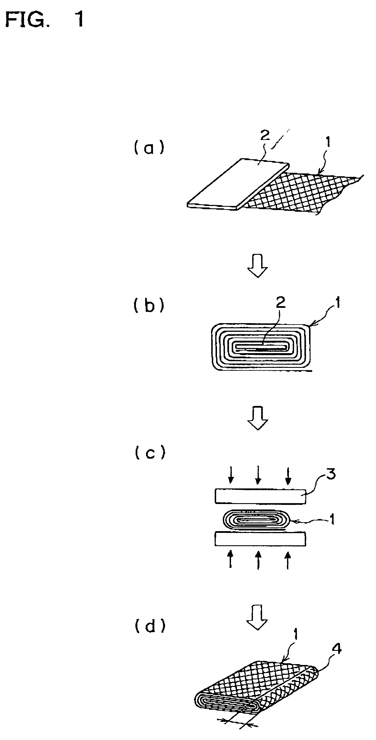
[0099] As shown in FIG. 1(a), ten sheets of band type mesh wire, each of which sheet has a thickness of 110 micron meter, a width of 100 mm, a length of 663 mm and 100 meshes were layered. Then, the end of thus layered sheets were aligned with a metal plate having a width of about 48 mm. Then, as shown in FIG. 1(b), the layered sheets of the band type mesh wire were wound around the metal plate. Then, the metal plate was removed from the wound mesh body, and as shown in FIG. 1(c), the force of 150 to 200 kgf / cm2 was applied so as to press the wound mesh body. Thus, the compressed mesh wick of about 51 mm.times.100 mm was prepared. The thickness of the compressed mesh wick was up to about 1.5 mm. The end portion of the wound mesh wick was prepared in such manner that the length of the end portion was about 5 mm from the tip of the side portion of the compressed mesh wick, as shown in FIG. 1(d). As a result, it was possible to remarkably reduce the gap between the layers of t...
example 2
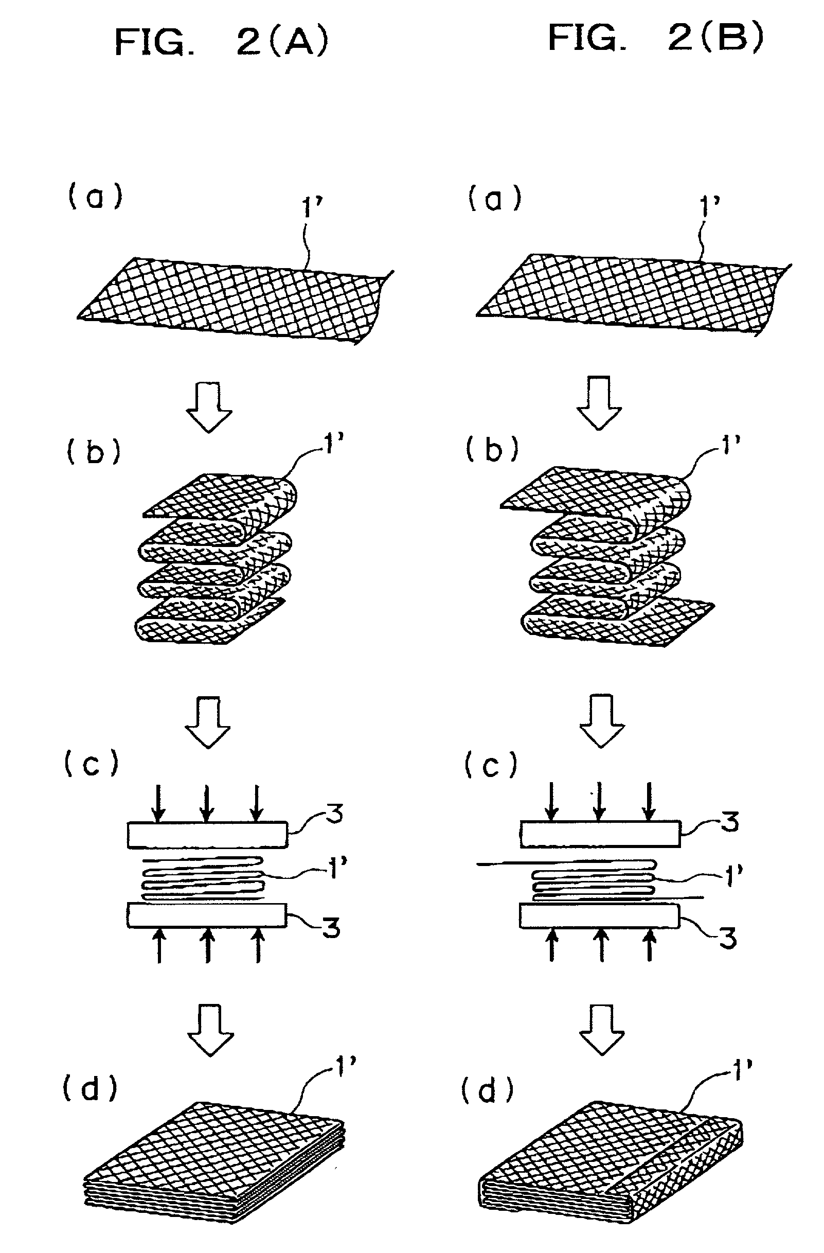
[0101] As shown in FIG. 2A(a), ten sheets of band type mesh wire, each of which sheet has a thickness of 110 micron meter, a width of 100 mm, a length of 663 mm and 100 meshes were layered. Then, as shown in FIG. 2A(b), a corrugated bent layered mesh body was prepared by bending the band type mesh wire in a corrugated form. Then, as shown in FIG. 2A(c), the force of 150 to 200 kgf / cm2 was applied to the corrugated bent layered mesh body so as to press same. Thus, the compressed mesh wick of about 51 mm.times.100 mm was prepared. The thickness of the compressed mesh wick was up to about 1.5 mm. As a result, it was possible to remarkably reduce the gap between the layers of the mesh wire. In addition, fine wires were not protrude outward and scattered.
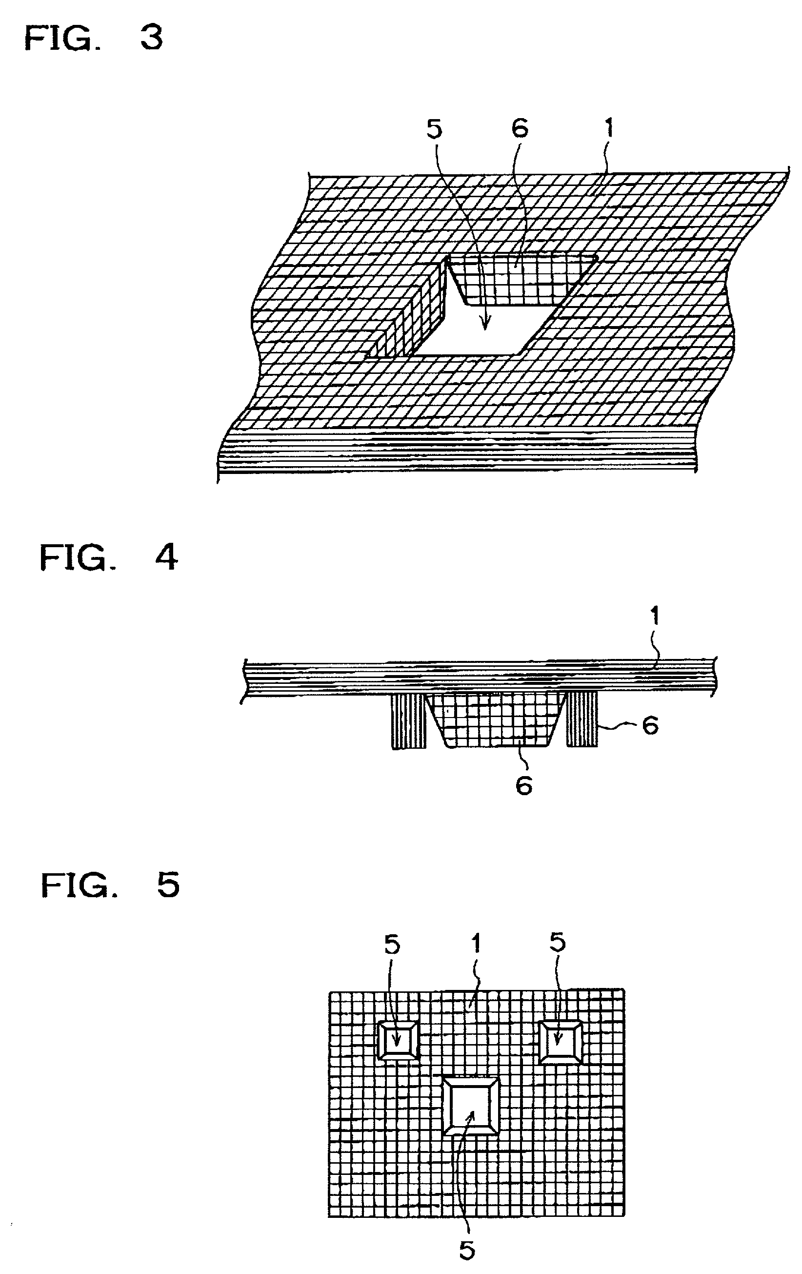
[0102] Thus prepared compressed mesh wick was press-attached to the inner wall of the heat dissipating side and the side wall of the heat transfer block by the spot welding, as shown in FIG. 6. As a result, the heat pipe having excellent...
PUM
 Abstract
Description
Claims
Application Information