Drain valve sealed by pressure-equalizing water film

A drainage valve and water film technology, which is applied to parts of pumping devices for elastic fluids, non-variable pumps, radial flow pumps, etc., can solve the problem of increased motor power, increased friction, failure, etc. Problems, achieve good dynamic sealing effect, reduce exhaust volume, and high air density

Pending Publication Date: 2022-07-19
MENGZHOU YUANHONG DRYING EQUIP RES & DEV CO LTD
View PDF1 Cites 0 Cited by
  • Summary
  • Abstract
  • Description
  • Claims
  • Application Information

AI Technical Summary

Problems solved by technology

The existing method has relatively large pressure or pressure loss, and the drainage cannot be continuous
[0003] There are many reasons for the leakage of the current drain valve: 1. Due to the presence of cracks, holes or protrusions on the inner wall of the valve, these tiny defects are large enough to reduce the quality of the dry seal on the flat surface, resulting in There is a gap on the wall sealing surface, causing leakage problems
2. The sealing strip and the inner wall of the valve are hard-sealed, which may cause rapid wear of the sealing strip and the inner wall of the valve and cause the seal to fail
3. The dust on the sealing device is not easy to remove dust, and the sealing device with dust adhesion will cause the sealing device to wear and leak
4. There is an excessive pressure difference on both sides of the sealing part, so the pressure transmitted to the sealing surface also increases, the friction between the impeller and the valve body increases, and the power of the motor that drives the impeller to rotate also increases
[0004] Existing patented product vacuum drainage ball valve (publication number CN105020567), the design structure of its air extraction device and intake valve is complex, and the use process is cumbersome
6. The intake valve needs to be connected to the high-pressure pump of the air compressor to work
7. The air extraction device needs to be connected to the vacuum unit or vacuum chamber to work

Method used


Image

  • Drain valve sealed by pressure-equalizing water film
  • Drain valve sealed by pressure-equalizing water film

Examples


Embodiment

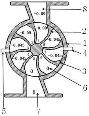
[0037] like figure 1 The shown drain valve sealed with a pressure-equalizing water film includes a valve body 1, an impeller 2, a porous material 3, and a conduit.

[0038] The valve body 1 has a water inlet 8 and a water outlet 7 on it.

[0039] The number of water bins 6 of the impeller 2 is eight.

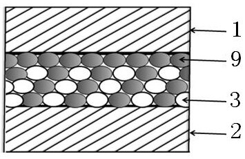
[0040] Said porous material 3 is a sponge.

[0041] like figure 1 , figure 2 One side of the shown porous material 3 is fixed on the surface of the impeller 2 , and the other side is attached to the valve body 1 .

[0042] The thickness of the porous material 3 is 5 mm.

[0043] The impeller 2 is in the inner cavity of the valve body 1 , and the water film seal between the impeller 2 and the valve body 1 is performed by the water 9 in the porous material 3 .

[0044] The intake valve 5 and the exhaust valve 4 of the valve body 1 are communicated by a conduit.

[0045] The present invention adopts a drain valve sealed by a pressure-equalizing water film for water discharg...


PUM


Abstract

The drain valve sealed by the pressure-equalizing water film comprises a valve body, an impeller, a porous material and a guide pipe. One side of the porous material is fixed on the surface of the impeller, and the other side is attached to the inner wall of the valve body. The motor drives the impeller to rotate and work, a water film adheres to the inner wall of the valve body, water film sealing is conducted between the impeller and the inner wall of the valve body through water in the porous material, and the air density of surface tension sealing is high. An intake valve and an exhaust valve on the valve body are communicated through a guide pipe, and different pressures in two water cabins, corresponding to the guide pipe, in the impeller are equalized; the pressure difference between the pressures in the adjacent water cabins above and below the impeller is small, the water film on the valve body also plays a role in lubrication, the friction force between the impeller and the valve body is reduced, and the power of a motor driving the impeller to rotate is also reduced. Impurities on the surface of the porous material are cleaned under the scouring action of water. Adjustment can be carried out according to the working requirements of vacuum equipment, the external condition limitation is few, and the application range is wide.

Description

technical field [0001] The invention relates to a drain valve, in particular to a drain valve sealed by a pressure-equalizing water film. Background technique [0002] The problem of condensed water discharge in the drying system and condensation system has always hindered the improvement of the working efficiency of vacuum drying, negative pressure drying and steam condensation. At present, the condensed water discharge methods of vacuum equipment include height difference discharge, vacuum drop discharge, and vacuum pressure difference discharge. The existing method has relatively large pressure or pressure loss, and the drainage cannot be continuous. [0003] There are many reasons for the leakage of the current drain valve: 1. Due to the existence of cracks, holes or protrusions on the inner wall of the valve body, these small defects are large enough to reduce the quality of the dry seal on the flat surface, causing the valve body to be damaged. There are gaps on the ...

Claims


Application Information

Patent Timeline
Patent Type & Authority Applications(China)
IPC IPC(8): F04D1/00F04D29/22F04D29/02F04D29/08
CPCF04D1/00F04D29/22F04D29/026F04D29/086
Inventor 程长青
Owner MENGZHOU YUANHONG DRYING EQUIP RES & DEV CO LTD
Why Eureka
Try Eureka