Circuit module and method for mounting the same

a technology of circuit modules and circuit boards, applied in the field of circuit modules, can solve the problems of circuit modules that cannot be lifted and carried by chucking devices, circuit modules cannot be chucked and lifted by chucking devices, and it is difficult to maintain the chucking plate parallel to the surface of multi-layer circuit boards

Inactive Publication Date: 2001-06-28
MURATA MFG CO LTD
View PDF0 Cites 6 Cited by
  • Summary
  • Abstract
  • Description
  • Claims
  • Application Information

AI Technical Summary

Problems solved by technology

With regard to a circuit module in which electronic components are mounted on a small circuit board at high density, however, the circuit module cannot be chucked and lifted by the chucking device since the electronic components form concavities and convexities on the circuit board.
Accordingly, even when a transformer having the above-described construction is used, the circuit module cannot be lifted and carried since the upper surfaces of the electronic components are not large enough to allow the required chucking force.
The electronic components mounted on the multi-layer circuit board, however, differ in height, and thus it is difficult to maintain the chucking plate parallel to the surface of the multi-layer circuit board.
Accordingly, there is a risk that the chucking plate will tilt relative to the multi-layer circuit board.
In addition, the cores fixed by the metal fitting rattle in the through holes formed in the multi-layer circuit board.
Accordingly, it

Method used


Image

  • Circuit module and method for mounting the same
  • Circuit module and method for mounting the same
  • Circuit module and method for mounting the same

Examples


second embodiment

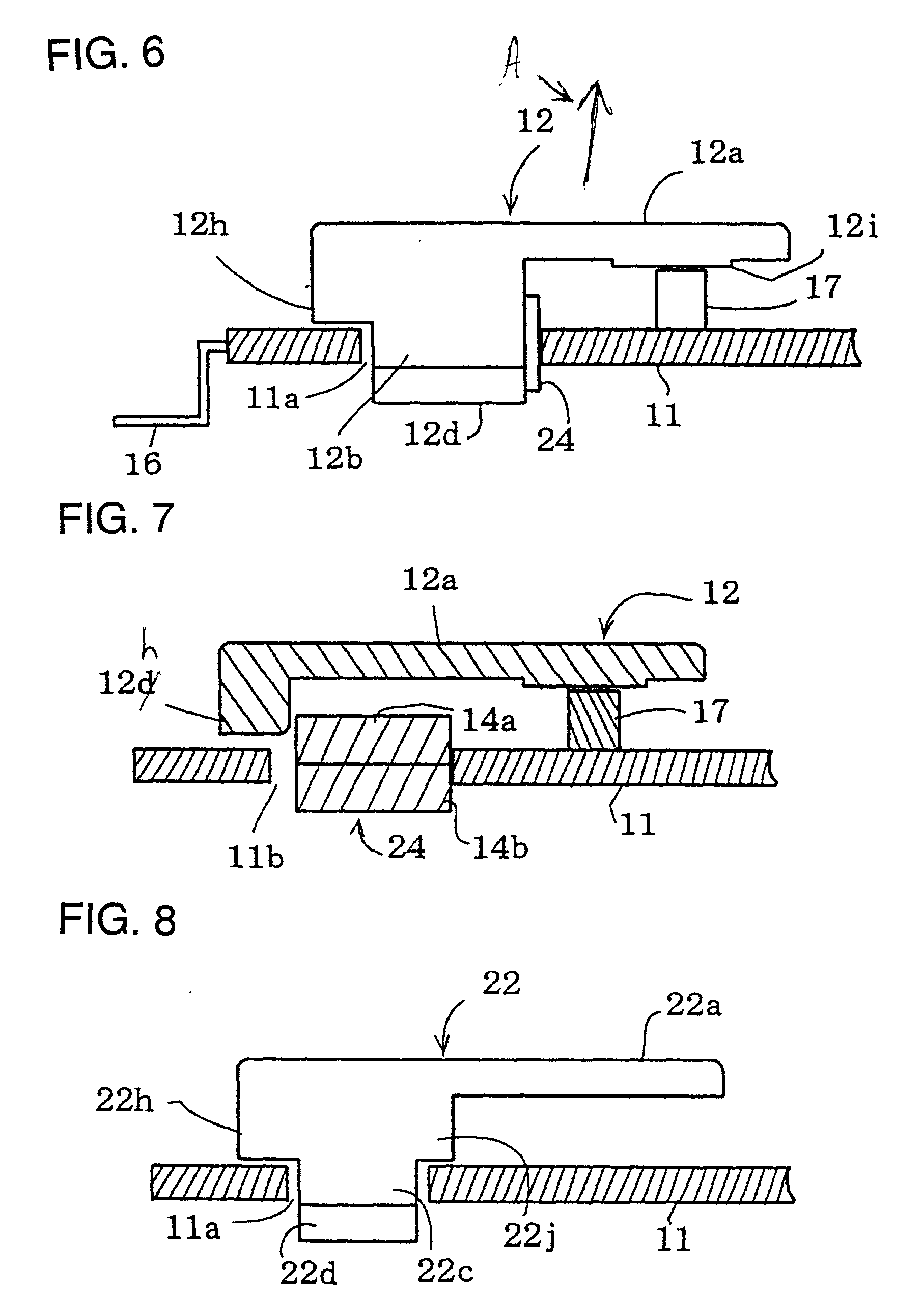
[0058] FIG. 8 shows a covering member incorporated in a The covering member 22 has a supporting portion 22c which is provided with two steps 22h and 22j. The supporting portion 22c is also provided with a hook portion 22d at the distal end, in a manner similar to that in FIG. 4. The end portion of the supporting portion 22c is inserted into the through holes 11a formed in the multi-layer circuit board 11. The steps 22h and 22j are pressed against the surface of the multi-layer circuit board 11, and the hook portion 22d is engaged with the edge of the through hole 11a at the bottom surface of the multi-layer circuit board 11. Accordingly, the steps 22h and 22j and the hook portion 22d clamp the multi-layer circuit board 11. With such a construction, the plate portion 22a is maintained parallel to the multi-layer circuit board 11 without utilizing one of the electronic components as a support. In this case, the protrusion 12i as shown in FIG. 6 is not necessary.

third embodiment

[0059] FIG. 9 shows a covering member incorporated in a A tongue piece 32d extends from the midsection of the pressing portion shown in FIG. 7. The tongue piece 32d is inserted into the middle through hole 11d along with the middle leg portions 14d of the cores 14, preventing the rattling of the cores.

fourth embodiment

[0060] FIG. 11 shows a covering member incorporated in a In contrast to the one shown in FIG. 4, the covering member 42 has supporting portions 42b and 42c which are provided with pressing portions 42e and 42d. The pressing portions 42e and 42d press the cores at the sides thereof, as in the case described above with reference to FIG. 4.

[0061] FIG. 12 shows a covering member and a core unit incorporated in another embodiment. The two E cores are fixed to each other by affixing the end surfaces 34a of the leg portions 14c, 14d, and 14e in the through holes 11a, 11b, and 11c with an adhesive, for example, an instantaneously bonding adhesive. Accordingly, the two E cores form a core unit 34. A plate portion 52a of a covering member 52 is provided with a resilient portion 52d which is protruding from the bottom surface. The resilient portion 52d is formed to have a thin arc shape, and has some degree of elasticity so that it can be deformed. Constructions and functions of the supportin...


PUM


Abstract

A circuit module has a covering member which has a plate portion and one or more supporting portions and a circuit board on which electronic components are mounted. The supporting portions fix the plate portion parallel to the surface of the circuit board. The covering member can be chucked by a chucking device to mount the circuit module to a mother circuit board.

Description

[0001] 1. Field of the Invention[0002] The present invention relates to circuit modules mounted in communication equipment, etc., and more particularly relates to a circuit module such as a surface mountable DC-DC converter. The present invention also relates to a method for mounting the circuit module on a mother circuit board incorporated in communication equipment, etc.[0003] 2. Description of the Related Art[0004] Recently, circuit boards incorporated in communication devices have been loaded with circuit modules along with various electronic components. From the viewpoint of working efficiency, the process of mounting the electronic components, etc., is preferably automated. To this end, each of the electronic components is formed to have a shape suitable for being chucked and carried by a chucking device. As described in Japanese Unexamined Patent Application Publication No. 8-107024, for example, a component such as a transformer formed by winding a conductive wire is covered...

Claims


Application Information

Patent Timeline
IPC IPC(8): H02M3/28H05K1/14H01F27/02H05K1/16H05K1/18H05K3/30H05K7/02
CPCH05K1/141H05K1/165H05K3/303H05K7/02H05K2201/086H05K2201/09063H05K2203/082
Inventor INOUE, KEIJIISHIGE, TSUTOMUOHTA, YOSHITERU
Owner MURATA MFG CO LTD
Why Eureka
Try Eureka