
Device for reading from and/or writing to optical recording media

Inactive Publication Date: 2001-07-05
THOMSON LICENSING SA
View PDF0 Cites 4 Cited by
  • Summary
  • Abstract
  • Description
  • Claims
  • Application Information

AI Technical Summary

Benefits of technology

[0005] An object of the invention is to improve a device of this type for reading from or writing to optical recording media, in particular also with regard to reducing the production costs.
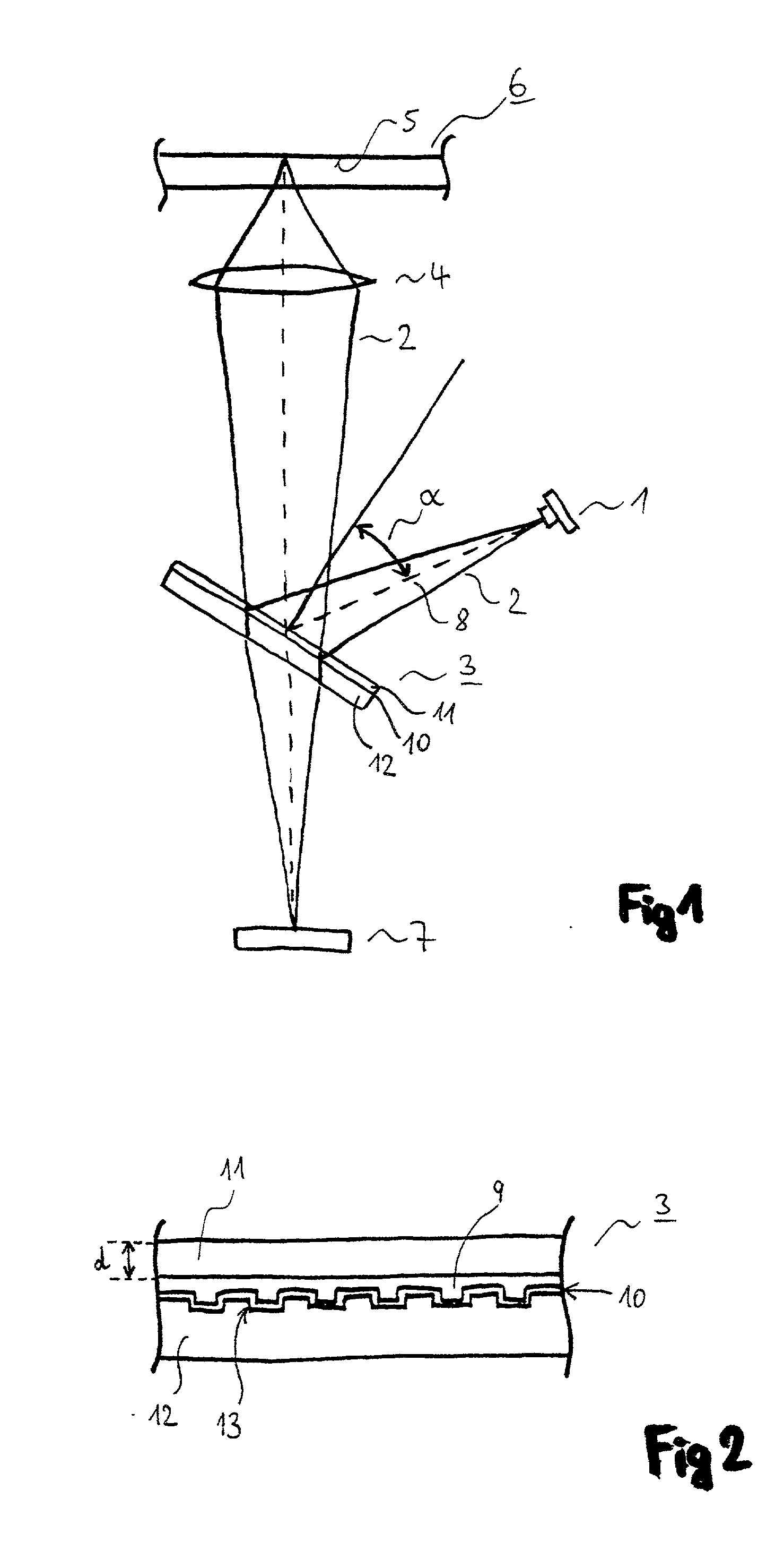
[0006] According to the invention, it is provided for this purpose that the semi-transparent mirror is a plane-parallel plate with a layered structure, a partially reflective layer being arranged between two small carrier plates. This has the advantage that the reflective layer is protected by the carrier plates against external influences of a mechanical, chemical or other nature, both before and during the production of the device as well as during its operation.
[0007] According to the invention, it is also envisaged to arrange a grating structure between the carrier plates. This has the advantage that a grating structure which is required in any case in the device, for example for producing primary and secondary scanning beams, or influencing the beam in some other way, for example by a hologram grating structure, is integrated into the semi-transparent mirror. The grating structure is consequently also protected against external influences. This dispenses with a component which otherwise has to be separately made and installed, and dispenses with the corresponding effort for its adjustment. The grating structure is in this case preferably applied to one of the carrier plates, or is formed into it, and is provided with the reflective layer. According to one variant, a complementary structure is provided directly on the other carrier plate. According to a further variant, a layer of adhesive is arranged on the reflective layer, which essentially has the grating structure of the carrier plate lying underneath it, and the said layer of adhesive fastens the other carrier plate on the first carrier plate. A further advantage of the grating structure arranged between the carrier plates is that it is effective only in reflection, since in this case phase differences occur between the waves reflected at the elevations and the waves reflected at the depressions of the grating structure. In transmission through both carrier plates, on the other hand, the grating structure has no, or virtually no, effect on the phase of the waves of the scanning beam. This applies if the refractive indices of the individual layers essentially coincide.
[0008] According to one embodiment of the invention, at least one of the carrier plates has a defined thickness. This has the advantage that a defined astigmatism is produced by this carrier plate of a defined thickness in the beam passing through it. The beam coming from the light source usually already has astigmatism, in particular if a laser diode, which has no means of compensating for astigmatism, is used as the light source. The thickness of the carrier plate of a defined thickness is adapted to the astigmatism of the beam emerging from the light source in such a way that the astigmatism produced by the carrier plate compensates as well as possible for the already existing astigmatism of the beam. Consequently, a scanning beam free from astigmatism falls on the recording medium. This leads to a reduction in possible scanning errors and to the avoidance of focusing errors, in particular whenever a focusing method using astigmatism is used for focusing the scanning beam onto an information-carrying layer of the recording medium.
[0009] It is provided according to the invention that the semi-transparent mirror is arranged at a defined angle with respect to the optical axis of the scanning beam coming from the light source. This has the advantage that no separate compensation for the astigmatism in the scanning beam produced by the light source is required. Both the thickness of the carrier plate and its angle in relation to the optical axis are optimally set according to the invention for astigmatism compensation. The angle is fixed in this case, at least for a certain type of light source, according to the magnitude of the astigmatism of the scanning beam produced by this light source. The angle preferably lies in the range of 30.degree., while an angle of 45.degree. is usually provided. During the assembly of the device, adjustment of the light source in the direction of rotation about the optical axis is carried out, whereby the optimum alignment with respect to the mirror for astigmatism compensation is achieved.
[0010] According to the invention, it is provided that the light source of the device is an unpackaged laser diode. This has the advantage that it is a low-cost component. The disadvantages of a laser diode not packaged in a housing, in particular that of the uncompensated astigmatism, are overcome by the arrangement and design of the semi-transparent mirror according to the invention.

Problems solved by technology

To be regarded as a disadvantage of the known device is that, in the case of the semi-transparent mirror, a reflective layer is arranged on the surface of a carrier element.
There is therefore the risk of the reflective layer being adversely affected by external influences.
Therefore, rejects must be expected during production, or increased expenditure for the prevention of rejects must be expected.

Method used


Image

  • Device for reading from and/or writing to optical recording media

Examples


Embodiment Construction

[0014] FIG. 1 shows a device according to the invention in a schematic representation. A laser diode 1, which has no astigmatism-compensating element, produces a scanning beam 2 provided with astigmatism. This falls on a semi-transparent mirror 3, is reflected by the latter and focused by means of an objective lens 4 onto an information-carrying layer of an optical recording medium 6. The recording medium 6 is shown only partially and in a sectioned representation. The information-carrying layer 5 has date markings, which are preferably arranged along a spiral or circular track and influence at least one of the properties of the scanning beam 2 when the latter is reflected. In the simplest case, the intensity of the reflected beam is concerned here, that it is to say a difference between light and dark. Here, too, other beam-influencing possibilities familiar to a person skilled in the art can also be meaningfully used. The reflected scanning beam 2 returns through the objective len...


PUM


Abstract

The present invention relates to a device for reading from and / or writing to optical recording media (6), which has a light source (1) for producing a scanning beam (2), a photodetector (7) for detecting the scanning beam (2) reflected by the recording medium (6) and a semi-transparent mirror (3) arranged in the beam path for directing the scanning beam (2) onto the recording medium (6) and the reflected scanning beam (2) onto the photodetector (7). The object of the invention is to improve a device of this type, in particular also with regard to reducing the production costs. This object is achieved by the semi-transparent mirror (3) being a plane-parallel plate with a layered structure, a partially reflective layer (10) being arranged between two small carrier plates (11, 12).

Description

[0001] The present invention relates to a device for reading from and / or writing to optical recording media, which has a light source for producing a scanning beam, a photodetector for detecting the scanning beam reflected by the recording medium and a semi-transparent mirror for directing the scanning beam onto the recording medium and the reflected scanning beam onto the photodetector.[0002] 1. Background of the Invention[0003] A device of this type is known from EP-A-0 198 655. To be regarded as a disadvantage of the known device is that, in the case of the semi-transparent mirror, a reflective layer is arranged on the surface of a carrier element. There is therefore the risk of the reflective layer being adversely affected by external influences. Therefore, rejects must be expected during production, or increased expenditure for the prevention of rejects must be expected.[0004] 2. Summary of the Invention[0005] An object of the invention is to improve a device of this type for r...

Claims


Application Information

Patent Timeline
IPC IPC(8): G02B5/08G02B5/18G11B7/135
CPCG11B7/1353G11B7/1362G11B7/1365
Inventor MORIMOTO, YASUAKIZUCKER, FRIEDHELMBUCHLER, CHRISTIAN
Owner THOMSON LICENSING SA
Learn More