

Monolithic capacitor
a technology of monolithic capacitors and capacitors, applied in the field of monolithic capacitors, can solve problems such as the reduction of electrostatic capacity
- Summary
- Abstract
- Description
- Claims
- Application Information
AI Technical Summary
Benefits of technology
Problems solved by technology
Method used
Image

Examples
Embodiment Construction
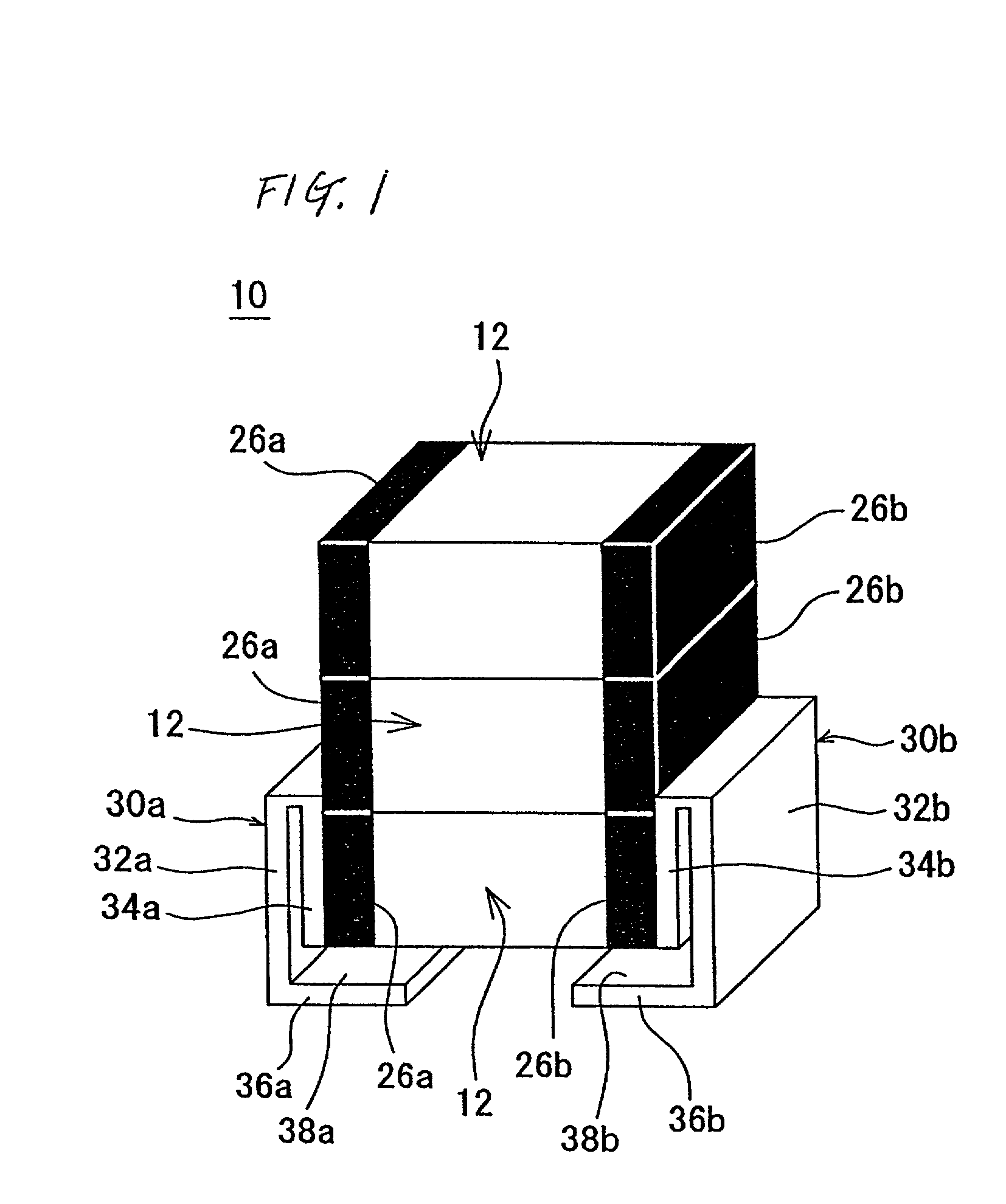
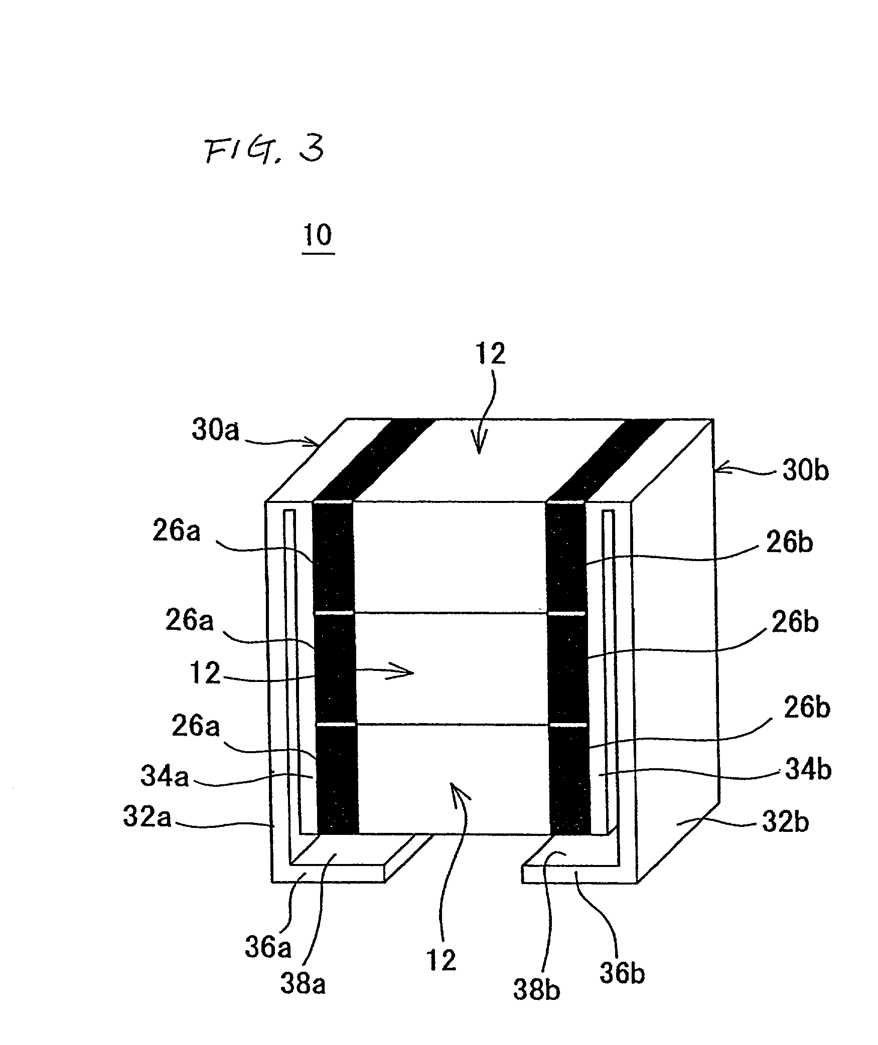
(FIG. 1) 2.5 Fe--Cr 0 / 36 0 / 36 Example 2 (FIG. 3) 7.0 Fe--Cr 0 / 36 0 / 36 Comparative 2.5 Fe--Cr 2 / 36 16 / 36 Example 1 (FIG. 4) Comparative 7.0 Fe--Cr 2 / 36 10 / 36 Example 2 (FIG. 6)
[0035] As is clear from Table 1, in Examples 1 and 2 constructed according to the first and second preferred embodiments of the present invention, in which solder layers were disposed on the entire surfaces of the external electrodes of the monolithic ceramic capacitor elements, the number of defects caused by thermal shock was zero. In contrast, in Comparative Examples 1 and 2 in which solder layers were partially formed on the surfaces of the external electrodes of the monolithic ceramic capacitor elements, defects occurred due to thermal shock.
[0036] This result occurred because when the external electrodes of the monolithic ceramic capacitor elements are partially connected by the solder layers, in the thermal shock cycle test, thermal stress is concentrated at the joints and cracks occur in the joints and ...
PUM
| Property | Measurement | Unit |
|---|---|---|
| thickness | aaaaa | aaaaa |
| thickness | aaaaa | aaaaa |
| thickness | aaaaa | aaaaa |
Abstract
Description
Claims
Application Information