
Pneumatic radial tire and method for manufacturing same

a technology of pneumatic radial tires and radial tires, which is applied in the direction of tires, vehicle components, domestic applications, etc., can solve the problems of inability to withstand general use, temperature at the tread portion rapidly rises, and the adhesion between the metallic cord surface and the rubber in the belt is broken, so as to prevent the hooping effect of the band at the shoulder portions of the bel

Inactive Publication Date: 2001-07-19
KOJIMA YOSHIHIDE +4
View PDF0 Cites 36 Cited by
  • Summary
  • Abstract
  • Description
  • Claims
  • Application Information

AI Technical Summary

Benefits of technology

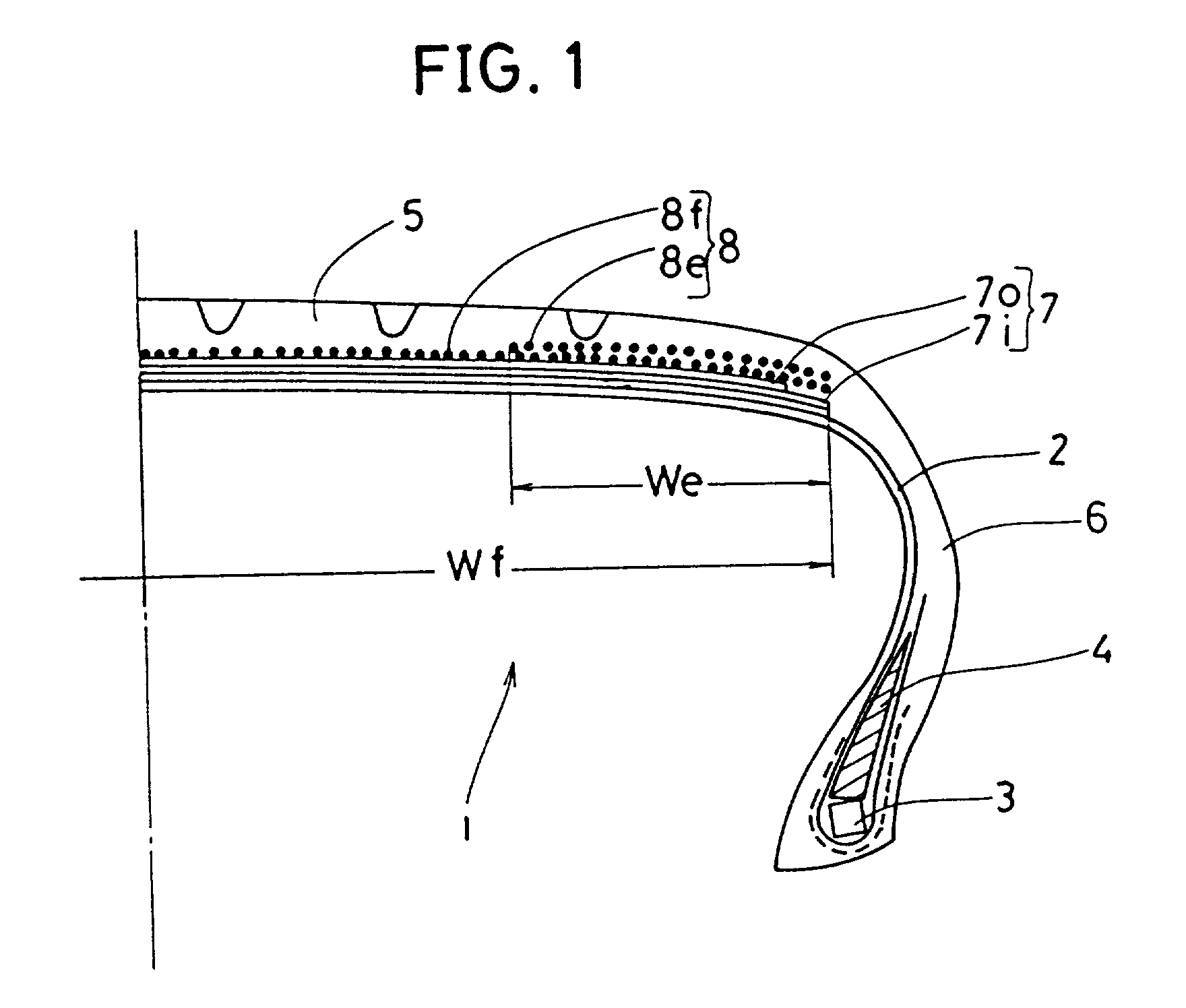
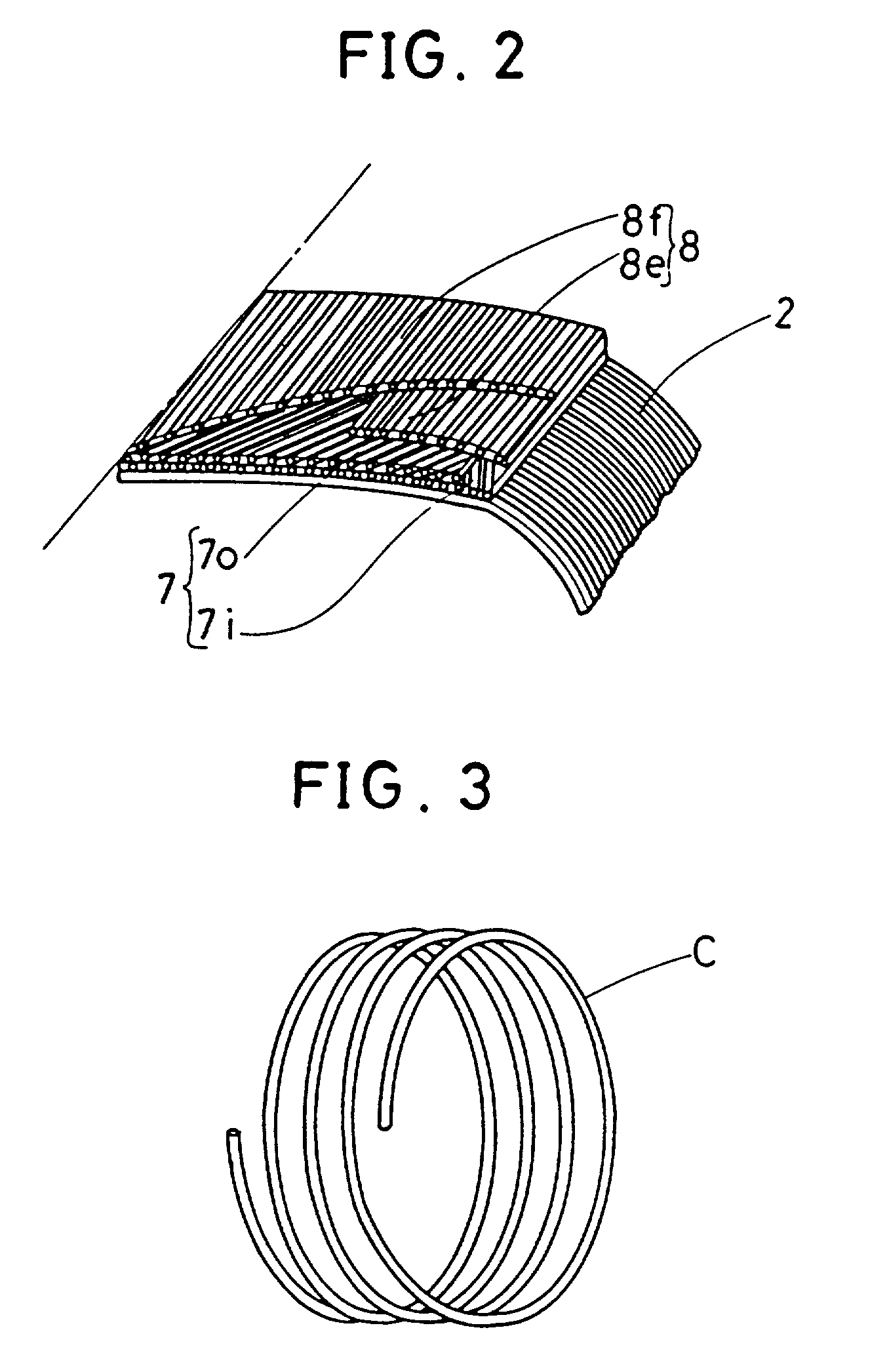
[0100] Also, the organic fiber cord C is preferably wound so that the radius of curvature at the section of the band in forming coincides with the radius of curvature of the band in the finished tire, in order that the difference between the stretch at the center of the band and the stretch at the shoulder portions falls within 2% (this will be explained in more detail in the method for forming an assembly of belt, band and tread rubber of this invention mentioned after. By doing so, the residual elongation or thermal shrinking force of the organic fiber cord of the band in the finished tire becomes uniform between the center portion and the shoulder portions or becomes higher at the shoulder portions, thus the lowering of the hooping effect of the band at the shoulder portions of the belt can be prevented.
[0223] Further, according to this invention, since the belt drum is deformed in a convex shape after winding belt on the cylindrical belt drum, and thereon one tape-like material formed by covering one to several cords with a rubber is spirally wound to adhere it tightly on the entire width of the belt drum, the belt is prevented from unusual moving when winding the band, and hence the belt is free from deformation, crease slack. Still more, in the method of this invention, since the belt is wound on a cylindrical belt drum, the belt can be wound in rood alignment. without causing meandering, when winding. Furthermore, in the device and the method of this invention, since the belt drum is an annular body continuous in the circumferential direction, different from a conventional segment type in which the drum surface is formed by segments, it becomes possible to adhere the belt without steps, especially at both ends of the both sides in the circumferential direction, and therefore the corrugated application as experienced by the conventional type drum is avoided, and separation damage of the belt shoulder portion can be prevented.

Problems solved by technology

In the field of racing cars, machines driving at such a speed range already exist, but the driving is only in a limited condition, so that the tires mounted on them have been manufactured by sacrificing general performances required in ordinary driving, for example, wearing resistance and fuel economy.
They are hence unable to withstand the general use.
Furthermore, owing to the heat generated by the repeated distortion in the tread caused by such a deformation, the temperature at the tread portion rapidly rises and the adhesion between the metallic cord surface and the rubber in the belt is broken; that is, so-called ply separation occurs.
Use of a rubber with a small loss tangent (tan .delta.) is effective for decrease of the heat generation, but when such a rubber with a small loss tangent (tan .delta.) is employed, the grip lowers and required high motional performances are hard to obtain.
Also, decrease of the deformation at the tread portion without changing the formulation of the tread rubber can be achieved by raising the hooping effect of the belt, but if the number of plies of the belt composed of metallic cords is increased, the weight of the tire increases, thus exerting adverse effects on the high-speed property of the entire car.
The stiffness in the circumferential direction decreases at this joint portion, thus large distortion tends to occur to induce breakage.
In addition, the joint portion may impair the uniformity of the tire.
Accordingly, the band is not sufficient for use in the high speed range described above.
The tire having such a band makes no trouble in ordinary speed range but in a high speed range as fast as more than 200 km / h or more than 300 km / h, it is impossible to prevent deformations caused by the centrifugal force on the tread portion and no sufficient durability is obtained.
But this means has the problem that it takes much time to wind the cord, thus its productivity is inferior, and since the wound cord becomes asymmetrical at the section of the tire, the uniformity such as conicity is poor.
Furthermore, upon changing the cord density, if the density is set too high, the cord surfaces contact each other, which sometimes induces breakage at that point.
Consequently, one of the band characteristics, that is, a function to prevent the lifting phenomenon of the belt owing to the centrifugal force during running cannot be fully executed.
In other words, a reinforcing effect for the failure of the belt due to the lifting while running is insufficient.
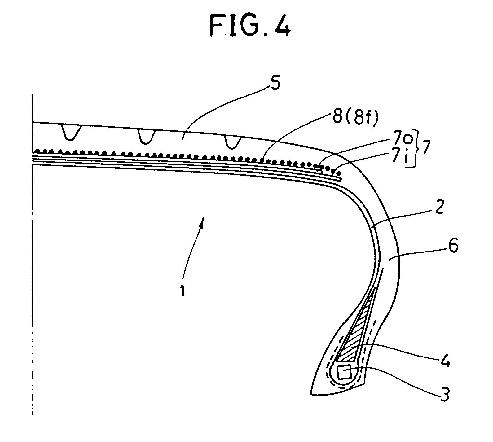
Such a problem results from the fact that the band is formed by winding on a cylindrical belt drum having a linear sectional shape in the axial direction as described above and shown in FIGS. 39, 40 and 22, in spite of the belt and band of the finished tire in the mold being convex in its sectional shape in the axial direction (final shape) as shown in FIG. 20.

Method used


Image

  • Pneumatic radial tire and method for manufacturing same
  • Pneumatic radial tire and method for manufacturing same
  • Pneumatic radial tire and method for manufacturing same

Examples


example 2 com

255 / 40 VR17 255 / 40 VR17 255 / 40 VR17 Belt material metal cord metal cord metal cord Number of belts 2 2 2 Angle of belt 24 degrees 24 degrees 24 degrees Carcass material polyester polyester polyester Structure of band full band full band full band 1 ply 1 ply 1 ply joint: none joint: none joint: present Band material nylon 66 nylon 66 nylon 66 1260d / 2 1260d / 2 1260d / 2 Cord diameter (d) 0.60 mm 0.60 mm 0.60 mm Rubber 0.15 mm 0.15 mm --thickness (t) Pitch (p) 0.90 mm 0.90 mm 0.90 mm Tension of cord in winding (T) Crown part 35 g 35 g --Shoulder part 45 g 45 g --Distribution of shoulder part shoulder part shoulder part elongation crown part > crown part under given shown in shown in shown in load of band cord Breaking speed 350 km / h 300 km / h 260 km / h

example 1

[0121] Example 1 has a distribution of elongation at given load of the cord of the full band layer as shown in FIG. 17.

[0122] Example 2 is similar to Example 1 in apparent structure, but the distribution of elongation at given load of the cord of the full band layer is reverse to the profile of Example 1 as shown in FIG. 18.

[0123] Comparative Example 1 wherein on the belt was provided a conventional full band layer possessing a joint extending in the widthwise direction at one position in the circumferential direction of the tire, has a distribution of elongation at given load of the cord of the full band layer as shown in FIG. 19.

[0124] As a result of indoor durability test of these tires in the same conditions as mentioned above, Example 1 of this invention presented a marked improvement effect as compared with Comparative Example, and its durability performance was nearly equal to that of the structure with an intervening edge band layer mentioned above.

[0125] Also, in the case o...

first embodiment

[0153] the diameter expanding means is the one particularly called as segment method by the present applicant, and as shown in FIGS. 23 to 25, a plurality of segments 41, for example, 8 to 32 segments, having the predetermined width and length are arranged over the entire circumference radially inside of the forming annular body.

[0154] The segments 41 are made of a hard material, such as aluminum and iron. The sectional shape of each segment in the axial direction of the drum is the same as or similar to the sectional shape (final finished shape) of the band of the finished tire in the mold, and more practically a convex shape of which absolute value of the difference between the middle portion stretch of the band and the shoulder portion stretch is 0% to 2%. The length SL of each segment is determined by the number of segments, and the width SW is determined by the belt width.

[0155] Each segment is mounted on the rod of cylinder 42, and each cylinder is fixed to the base frame 12, ...


PUM


Abstract

A pneumatic radial tire and a method for manufacturing the same, a device for forming a band of radial tire, and a method of and device for forming a belt-band-tread rubber assembly. The pneumatic tire including a belt arranged on the radially outer side or a carcass, and a band arranged on the radially outer side of the belt and composed of continuous one to several organic fiber cords wound spirally and approximately parallel to the circumferential direction of the tire. The radial tire manufacturing method including the steps of laminating the predetermined number of belt plies on a belt drum or belt ring for forming a belt, and winding one to several organic fiber cords continuously and spirally in the cicumferential direction of the belt on the outer surface of the formed belt in order to form a band. The band forming device including a means for drawing out a cord to be wound, a means for traversing the letting-off means in the widthwise direction of the belt, and a means for controlling the traverse of the letting-off means. The method of forming belt-band-tread rubber assemblies comprising a step of expanding the diameter of belt drum so that the shape in axial section of belt drum becomes the same or approximately the same as the finished shape of the band in vulcanization mold. The assembly forming device including a diameter-variable belt drum comprising a stretchable forming annular body made of an elastomer, and a means for expanding and contracting the diameter of the annular body, wherein the shape in axial section of the circumferential surface of the annular body in the diameter.

Description

[0001] This invention relates to a pneumatic radial tire equipped with a band for reinforcing a belt and a method for manufacturing the same, and further relates to an apparatus for forming the band, and a method of and apparatus for forming a belt-band-tread rubber assembly.[0002] Pneumatic radial tires having a belt in which metallic cords are arranged and which is disposed in the tread portion have been conventionally attached to high performance passenger cars, and high-speed durability, high-speed driving stability and steerability have been accomplished owing to a strong hooping effect of the belt. The conventional speed range from 100 to 200 kw / h, however, has been accelerated these days, and some passenger cars driving at 200 km / h or more, and sometimes at 300 km / h, have been introduced. In the field of racing cars, machines driving at such a speed range already exist, but the driving is only in a limited condition, so that the tires mounted on them have been manufactured by...

Claims


Application Information

Patent Timeline
IPC IPC(8): B29D30/08B29D30/30B60C9/22
CPCB29D30/08B29D30/3028B60C9/2204Y10T152/10783B60C2009/2209
Inventor KOJIMA, YOSHIHIDESAKUNO, HIROAKITAKAMI, MASAOKADOWAKI, KATSUNORIMIYANAGA, YOSHINOBU
Owner KOJIMA YOSHIHIDE
Learn More