Ink jet mechanism with thermoelastic bend actuator having conductive and resistive beams

Inactive Publication Date: 2001-07-19
SILVERBROOK RES PTY LTD +1
View PDF0 Cites 62 Cited by
  • Summary
  • Abstract
  • Description
  • Claims
  • Application Information

AI Technical Summary

Benefits of technology

0012] According to the invention there is provided an ink jet nozzle assembly including a nozzle chamber having a nozzle, the chamber including a movable portion configured for movement to effect ejection of ink from the chamber via said nozzle, the assembly further including an actuator attached

Problems solved by technology

Each technology may have its own advantages and disadvantages in the areas of cost, speed, qual

Method used


Image

  • Ink jet mechanism with thermoelastic bend actuator having conductive and resistive beams
  • Ink jet mechanism with thermoelastic bend actuator having conductive and resistive beams
  • Ink jet mechanism with thermoelastic bend actuator having conductive and resistive beams

Examples


Embodiment Construction

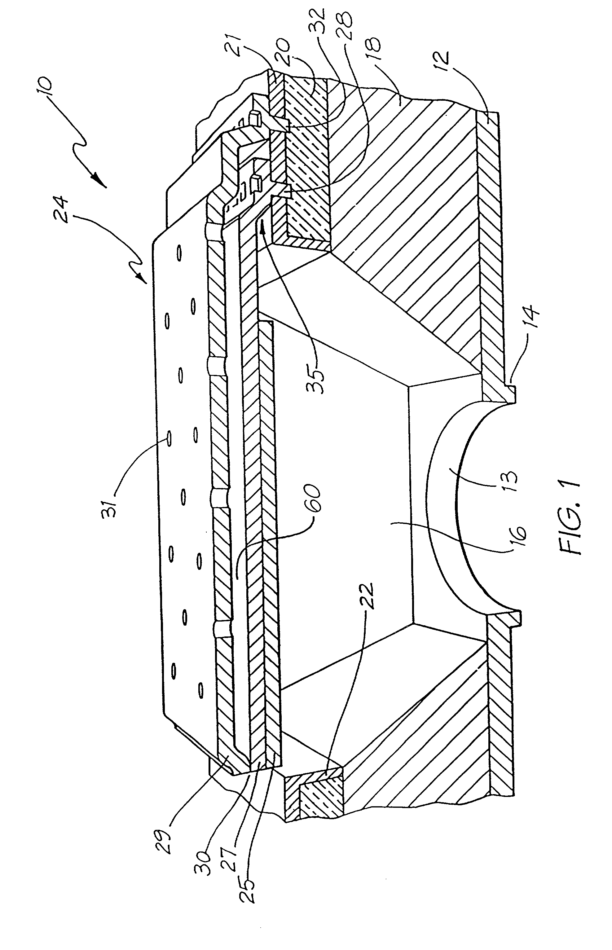
[0045] In the preferred embodiment, there is provided an ink jet printer having nozzle chambers. Each nozzle chamber includes a thermoelastic bend actuator that utilizes a planar resistive material in the construction of the bend actuator. The bend actuator is activated when it is required to eject ink from a chamber.

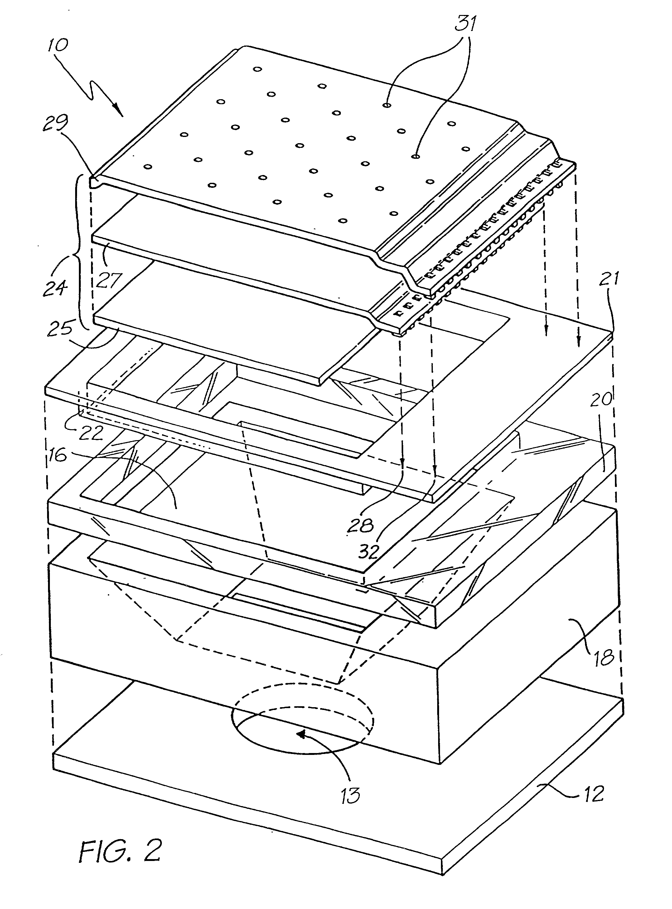
[0046] Turning now to FIG. 1, there is illustrated a cross-sectional view, partly in section of a nozzle arrangement 10 as constructed in accordance with the preferred embodiment. The nozzle arrangement 10 can be formed as part of an array of nozzles fabricated on a semi-conductor wafer utilizing techniques known in the production of micro-electro-mechanical systems (MEMS). For a general introduction to a micro-electric mechanical system (MEMS) reference is made to standard proceedings in this field including the proceedings of the SPIE (International Society for Optical Engineering), volumes 2642 and 2882 which contain the proceedings for recent advances and conference...


PUM


Abstract

An ink jet printer uses a planar thermoelastic bend actuator to eject ink from a nozzle chamber. The thermal actuator includes a lower planar surface constructed from a highly conductive material such as a semiconductor metal layer interconnected to an upper planar surface constructed from an electrically resistive material such as Indium Tin Oxide (ITO), such that, upon passing a current between the planar surfaces, the thermal actuator is caused to bend towards an ink ejection port so as to thereby cause ejection of ink from the ink ejection port. The actuator is attached to a substrate and further includes a stiff paddle portion which increases the degree of bending of the actuator near the point where it is attached to the substrate. The surfaces are further coated with a passivation material as required.

Description

[0001] This is a C-I-P of application Ser. No. 09 / 112,802 filed on Jul. 10, 1998.[0002] The present invention relates to ink jet printing and in particular discloses a planar thermoelastic bend actuator ink jet printer.[0003] The present invention further relates to the field of drop on demand ink jet printing.[0004] Many different types of printing have been invented, a large number of which are presently in use. The known forms of print have a variety of methods for marking the print media with a relevant marking media. Commonly used forms of printing include offset printing, laser printing and copying devices, dot matrix type impact printers, thermal paper printers, film recorders, thermal wax printers, dye sublimation printers and ink jet printers both of the drop on demand and continuous flow type. Each type of printer has its own advantages and problems when considering cost, speed, quality, reliability, simplicity of construction and operation etc.[0005] In recent years, the ...

Claims


Application Information

Patent Timeline
IPC IPC(8): B41J2/14B41J2/16
CPCB41J2/14427B41J2/1628B41J2/1629B41J2/1631B41J2/1632B41J2/1635B41J2/1639B41J2/1642B41J2/1645B41J2/1646B41J2/1648B41J2002/14435
Inventor SILVERBROOK, KIA
Owner SILVERBROOK RES PTY LTD
Why Eureka
Try Eureka