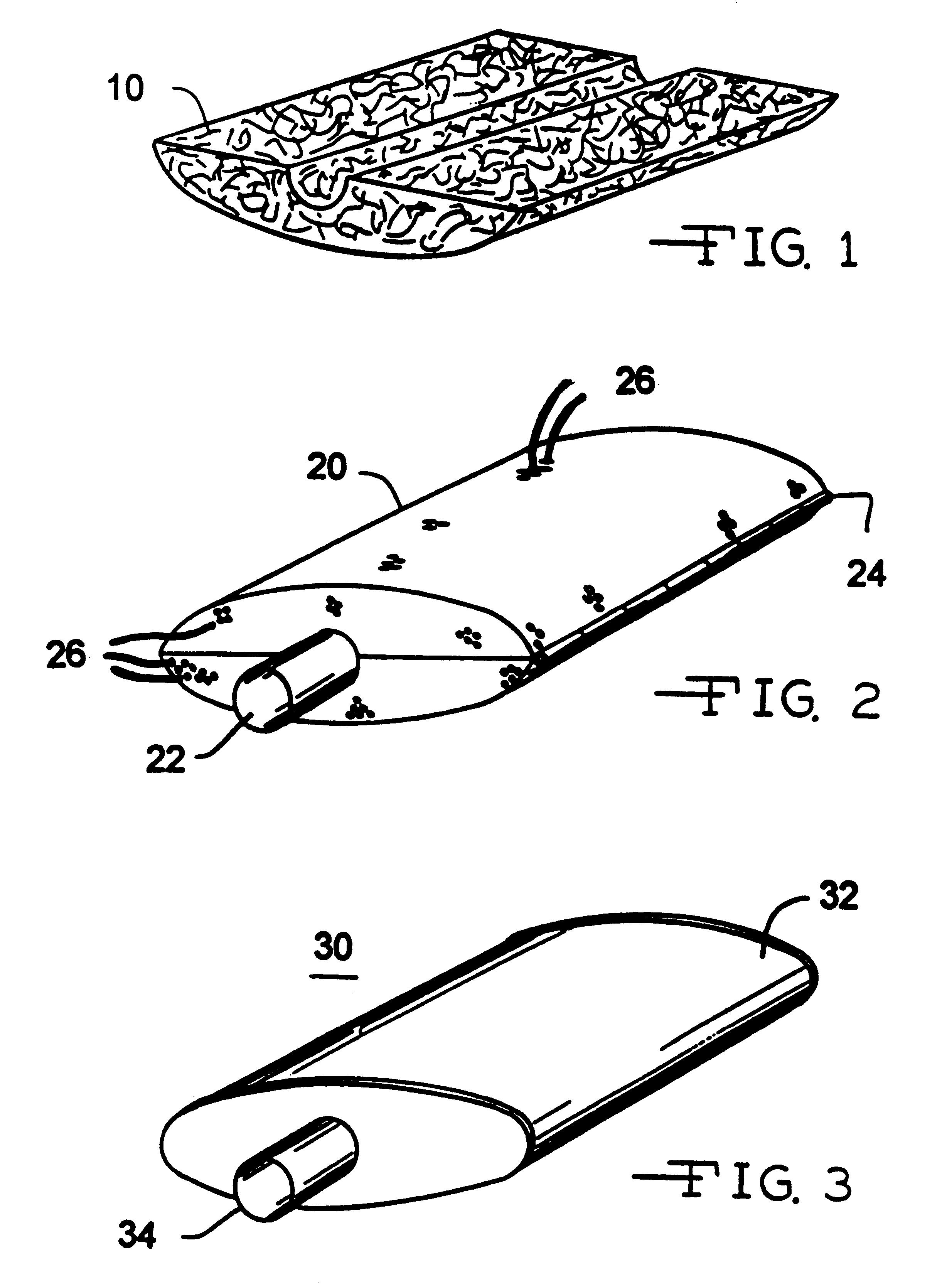
Preformed sound absorbing material for engine exhaust muffler

a technology of engine exhaust and preformed material, which is applied in the direction of machines/engines, manufacturing tools, mechanical equipment, etc., can solve the problems of clam shell mufflers, requiring specific tooling, machinery and capital expenses, and generally too heavy to bear, so as to improve aerodynamics, reduce specific tooling costs, and reduce the volume of mufflers produced

Inactive Publication Date: 2001-08-09
O C FIBERGLAS SWEDEN +1
View PDF0 Cites 33 Cited by
  • Summary
  • Abstract
  • Description
  • Claims
  • Application Information

AI Technical Summary

Benefits of technology

[0006] While the filling of mufflers can be made using the patented method of U.S. Pat. No. 4,569,471, my newer technique involves the making of preforms which are placed in the muffler before the muffler is assembled. A newer type of mufflers, the so-called "clam shell mufflers" are being developed progressively replacing previous elliptical or round shaped mufflers. They offer several advantages, in particular they offer a greater freedom from the standpoint of geometry allowing for better fit under the car bodies and better aerodynamics. Clam shell mufflers, however, require specific tooling, machinery and capital expenses for continuous E glass filling that are generally too heavy to bear if the volume of mufflers produced is small.
[0007] This invention does not require expensive tooling allowing one machine to produce many different types of mufflers with very low specific tooling costs. Another advantage of this invention allows more intricate shapes of clam shell mufflers to be filled with fluffed continuous glass fiber filaments. With the ease of producing my preforms, standardization of size and shape becomes less critical.

Problems solved by technology

Clam shell mufflers, however, require specific tooling, machinery and capital expenses for continuous E glass filling that are generally too heavy to bear if the volume of mufflers produced is small.

Method used


Image

  • Preformed sound absorbing material for engine exhaust muffler

Examples


Embodiment Construction

[0011] The present invention is compatible with any glass fiber conventionally utilized as reinforcements. The term "glass fibers" as used herein shall mean filaments formed by attenuation of one or more streams of molten glass or strands which are formed when such glass fiber filaments are gathered together in the forming process. The term shall also mean yarns and cords formed by applying and / or twisting a multiplicity of strands together. Preferably, the present invention uses E glass type fibers. Other reinforcement glass compositions may be used.

[0012] The glass fibers typically will be coated with a conventional size which allows the fibers to unwind and to expand or fluff when blown with air. Generally, the size may contain a carrier solvent, normally water, a coupling agent, a film former material and the like.

[0013] Sizing compositions typically employed as coatings for glass fibers are conventionally applied to the surface of the glass fibers after the glass fiber has been...


PUM

PropertyMeasurementUnit
temperatureaaaaaaaaaa
ambient temperaturesaaaaaaaaaa
particle sizeaaaaaaaaaa

Abstract

This invention provides preforms of continuous glass fiber strands for use as the sound absorbing material in an engine exhaust muffler. Preferably, the material is made of glass fibers of E glass compositions. With this invention, the strands are fluffed up, not directly in the muffler, but in a cavity that is made of a perforated shell matching the muffler shape. During this operation, a powder binder also is blown in with the fibers. This blowing operation is completed by forcing hot air through the preform which melts or cures the binder and allows it to bond the fibers together.

Description

[0001] This invention relates to preforms of continuous glass fiber strands for use as the sound deadening material in an engine exhaust muffler.[0002] Many mufflers include some sort of packing material or sound absorbing material located in the interior of the muffler for dampening the sound made by the escaping hot gases which pass through the muffler. While certain principles of sound attenuation have been recognized and utilized in various types of muffler designs, room for greatly improving muffler material remains. The advent of the clam shell muffler design also provides an opportunity to improve the sound deadening material.[0003] Conventional materials for mufflers can be any porous, sound deadening material, including sized, crushed mineral matter, mica, exfoliated vermiculite, brown slag, coke, pumice, or other porous aggregate material. Fiberglass wool from insulation glass often was used as a noise dampening filler. Mineral wool and rock wool preformed or in the shape ...

Claims


Application Information

Patent Timeline
Patent Type & Authority Applications(United States)
IPC IPC(8): B29B11/16B29C70/30D04H1/64F01N1/24F01N13/18
CPCB29B11/16B29C70/305D04H1/641F01N1/24F01N13/18F01N2310/02F01N2330/102F01N2450/06D04H1/587D04H1/60
Inventor KNUTSSON, GORAN
Owner O C FIBERGLAS SWEDEN
Why Eureka
Try Eureka