Device and method for the reduction of sound emissions in and diagnosis of internal combustion engines

a technology of internal combustion engine and sound emission reduction, which is applied in the direction of sound producing devices, ear treatment, musical instruments, etc., can solve the problems of increased exhaust gas back pressure, increased engine power loss and/or consumption, and silencers occupying considerable overall space in engine area or on the vehicle floor, so as to reduce the sound emissions of internal combustion engines and increase the sound compensation efficiency , the effect of easy installation in the exhaust lin

Inactive Publication Date: 2001-09-13
NAGEL FRIEDMUND
View PDF9 Cites 24 Cited by
  • Summary
  • Abstract
  • Description
  • Claims
  • Application Information

AI Technical Summary

Benefits of technology

0037] Therefore, a device and a method for reducing the sound emissions from internal combustion engines in an exhaust line are provided. Compensating for the noise at the noise source benefits the environment and the vehicle occupants alike. By arranging the second sound transducer centrally in the exhaust gas flow, optimum symmetrical, laterally limited acoustic conditions are created. The emission of compensating sound waves can be undertaken essentially parallel to the main sound oscillation plane, thereby achieving increased sound compensation efficiency. In contrast to the prior art, in which lateral sound compensation concepts are regularly developed, the present invention is based on a central sound compensation concept. The device can easily be fitted in the exhaust line without the need to undertake major design modifications. With the addition of a comparator unit, the device may also be used for the diagnosis of internal combustion engines. The condition of an internal combustion engine can thereby be determined at any time.

Problems solved by technology

Damping of the exhaust emissions in silencers leads to increased exhaust gas back pressure and hence to engine power loss and / or increased consumption.
In addition the silencers take up considerable overall space in the engine area or on the vehicle floor and constitute a significant weight addition to the vehicle.
When activated, the loudspeakers generate a cancelling noise.

Method used


Image

  • Device and method for the reduction of sound emissions in and diagnosis of internal combustion engines
  • Device and method for the reduction of sound emissions in and diagnosis of internal combustion engines

Examples


Embodiment Construction

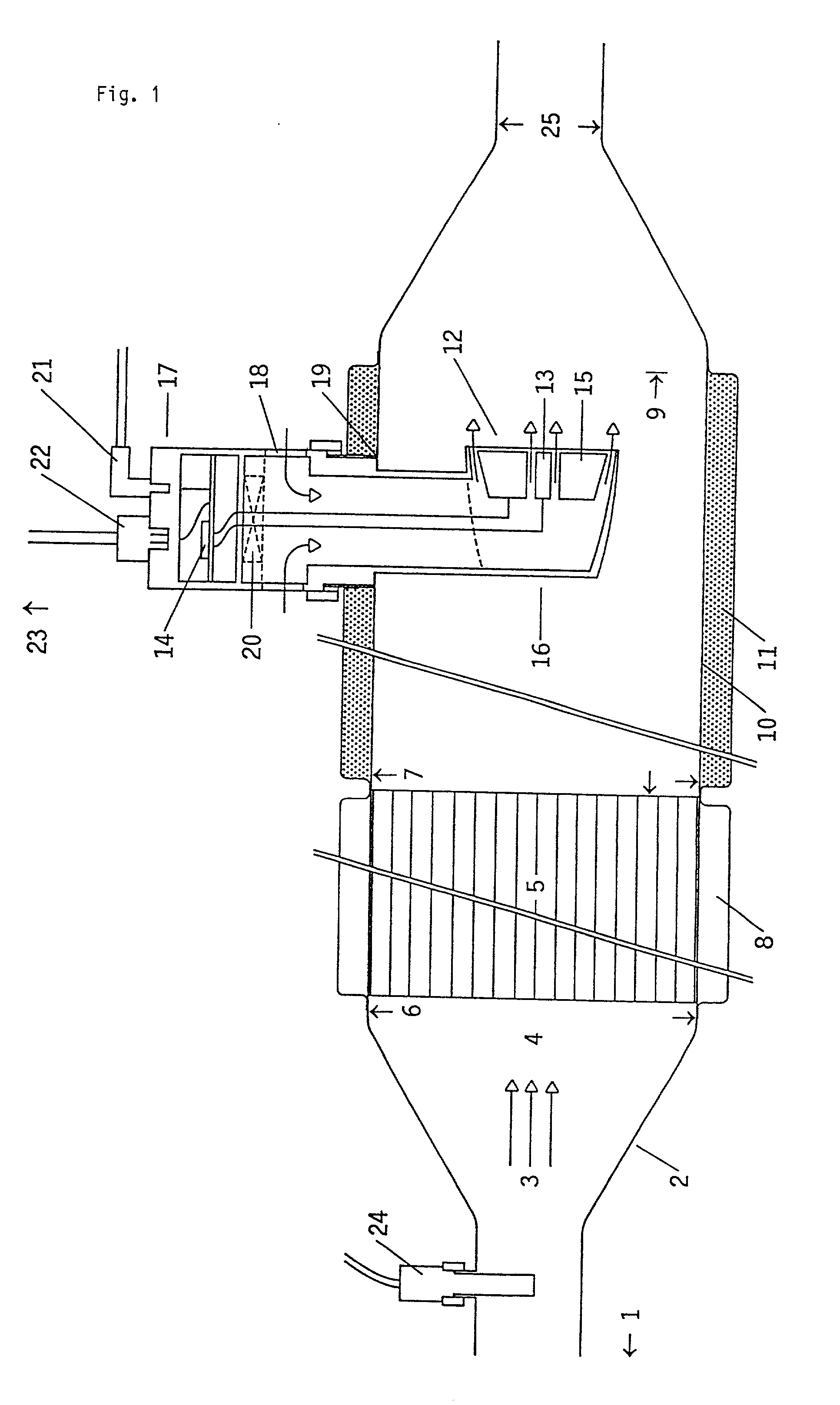
[0066] FIG. 1 shows an exhaust line 2 for the collection and removal of an exhaust gas flow 3, symbolized by multiple arrows, from an internal combustion engine 1 (not shown) which is arranged in the direction of the arrow 1. A widening 4 in the exhaust line 2 contains a catalytic converter 5 with air gap thermal insulation 8. The catalytic converter 5 may, for example, be a metal catalytic converter suitable for motor vehicles. An inlet 6 and an outlet 7 are provided for the exhaust gas flow 3. The catalytic converter's internal structure is selected in such a way that the exhaust gas flow 3 leaves the catalytic converter 5 at its outlet 7 in a largely parallel, irrotational gas flow.

[0067] The catalytic converter 5 shown here produces a rectification of the sound field of the exhaust gas flow 3. The sound field is largely non-directional upstream of the catalytic converter 5. The components of the sound waves that are perpendicular to the longitudinal axis of the catalytic convert...


PUM


Abstract

A device and a method for the reduction of sound emissions from an internal combustion engine in an exhaust line carrying an exhaust gas flow. The device has a first sound transducer for converting sound waves into first signals, that are a measure of the frequency, amplitude and phase of the sound waves, an electronic control unit for converting the first signals into second signals, and a second sound transducer, that is centrally arranged in the exhaust gas flow for converting the second signals into compensating sound waves, that have a frequency, amplitude, and phase such that the sound waves and the compensating sound waves at least partially cancel one another out. The device may also be used for diagnosis of the condition and running of the internal combustion engine. If so, the device may include a comparator unit, in which the first signals are compared with reference signals.

Description

FIELD OF THE INVENTION[0001] The present invention relates to a device and a method for the reduction of sound emissions from internal combustion engines and for the diagnosis thereof.DESCRIPTION OF THE RELATED ART[0002] Internal combustion engines such as those used in automobiles, motor cycles, and small-power motor appliances such as lawnmowers and power saws continuously emit exhaust gases from the combustion chamber into the surroundings. These exhaust gases are set in oscillation by the combustion process and, as a result, constitute a sound source of considerable intensity.[0003] Silencers are conventionally arranged in the exhaust flow of internal combustion engines in order to damp the oscillations and hence reduce the sound emissions of the exhaust gases. In motor cars, two silencers, a front silencer and a rear silencer, are often used. The function of the front silencer is nowadays often assumed by a catalytic converter used for exhaust emission control. Damping of the e...

Claims


Application Information

Patent Timeline
Patent Type & Authority Applications(United States)
IPC IPC(8): F01N1/06F01N3/28G10K11/178
CPCF01N1/065F01N3/2885F01N2230/04F05B2260/962G10K11/1788G10K11/17875G10K2210/12822G10K2210/3217G10K11/17857Y02A50/20
Inventor NAGEL, FRIEDMUND
Owner NAGEL FRIEDMUND
Why Eureka
Try Eureka