
Device and method for applying adhesive to materials such as strands

a technology of adhesive and strands, which is applied in the direction of lighting and heating apparatus, insulation conductors/cables, combustion types, etc., can solve the problems of strand material being severed, troublesome operation and extra time, and the adhesive coating device is known, so as to prevent the irregular swing of the adhesive and prevent the effect of adhesion of dus

Inactive Publication Date: 2001-09-20
NORDSON CORP
View PDF62 Cites 29 Cited by
  • Summary
  • Abstract
  • Description
  • Claims
  • Application Information

AI Technical Summary

Benefits of technology

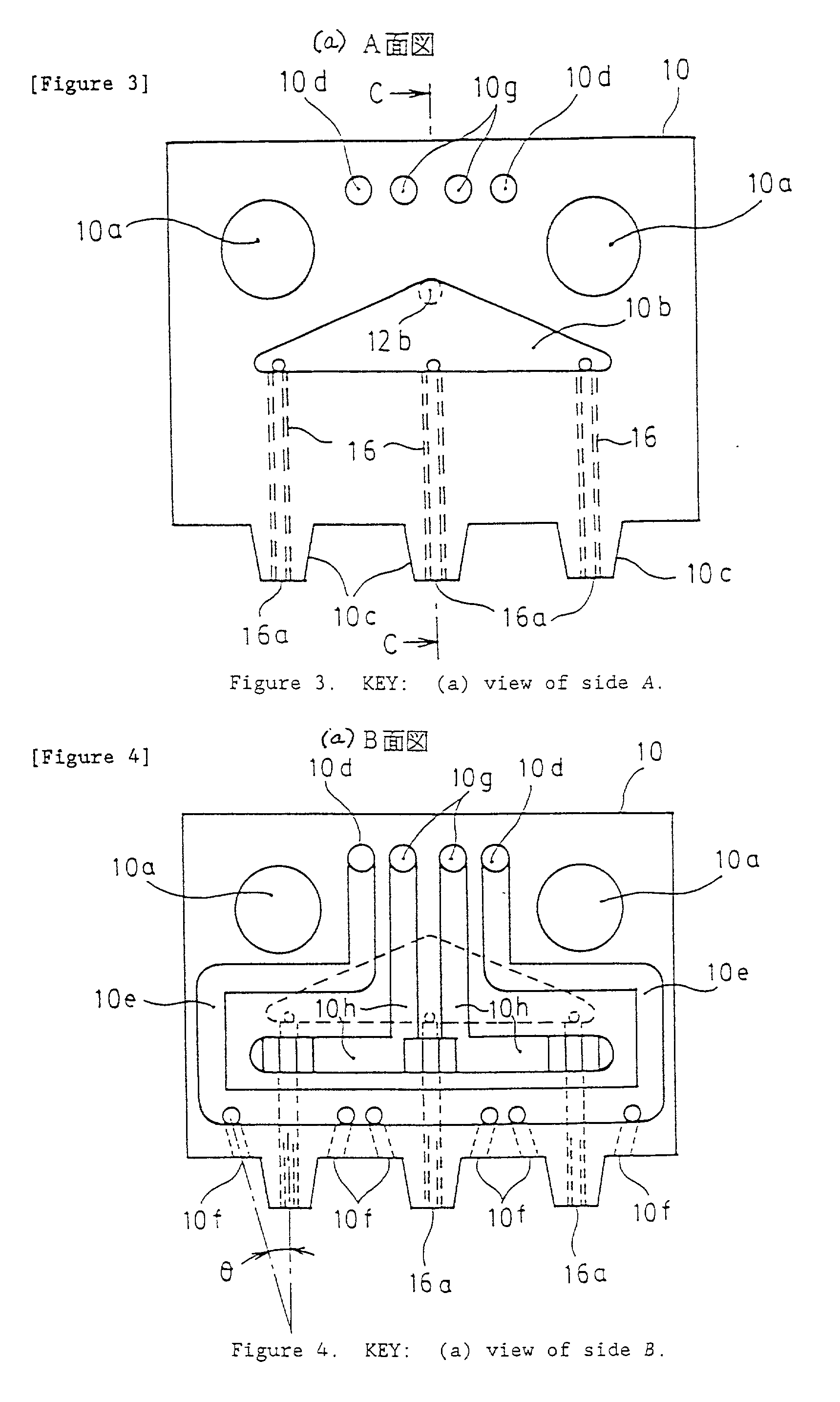
[0022] The two sets of air discharge orifices have different advantageous functions each in association with the corresponding liquid discharge orifice. The pattern air discharge orifices vacillate the first bead of adhesive back and forth in a vacillating plane containing the first and second pattern air discharge orifices. The first and second cleaning and stabilizing air discharge orifices emit jets of air in a direction parallel to the first axis to clear airborne contaminants, such as dust, away from the first liquid discharge orifice and to stabilize the first bead of adhesive in the vacillation plane. Thus, not only do the cleaning and stabilizing air discharge orifices clean the nozzle of contaminants, such as dust which may clog the liquid discharge orifice, they also help maintain the vacillating adhesive bead in a single plane, which is generally a plane perpendicular to the machine direction of the material. This ensures a more uniform adhesive bead pattern and, therefore, more accurate and consistent bead placement.
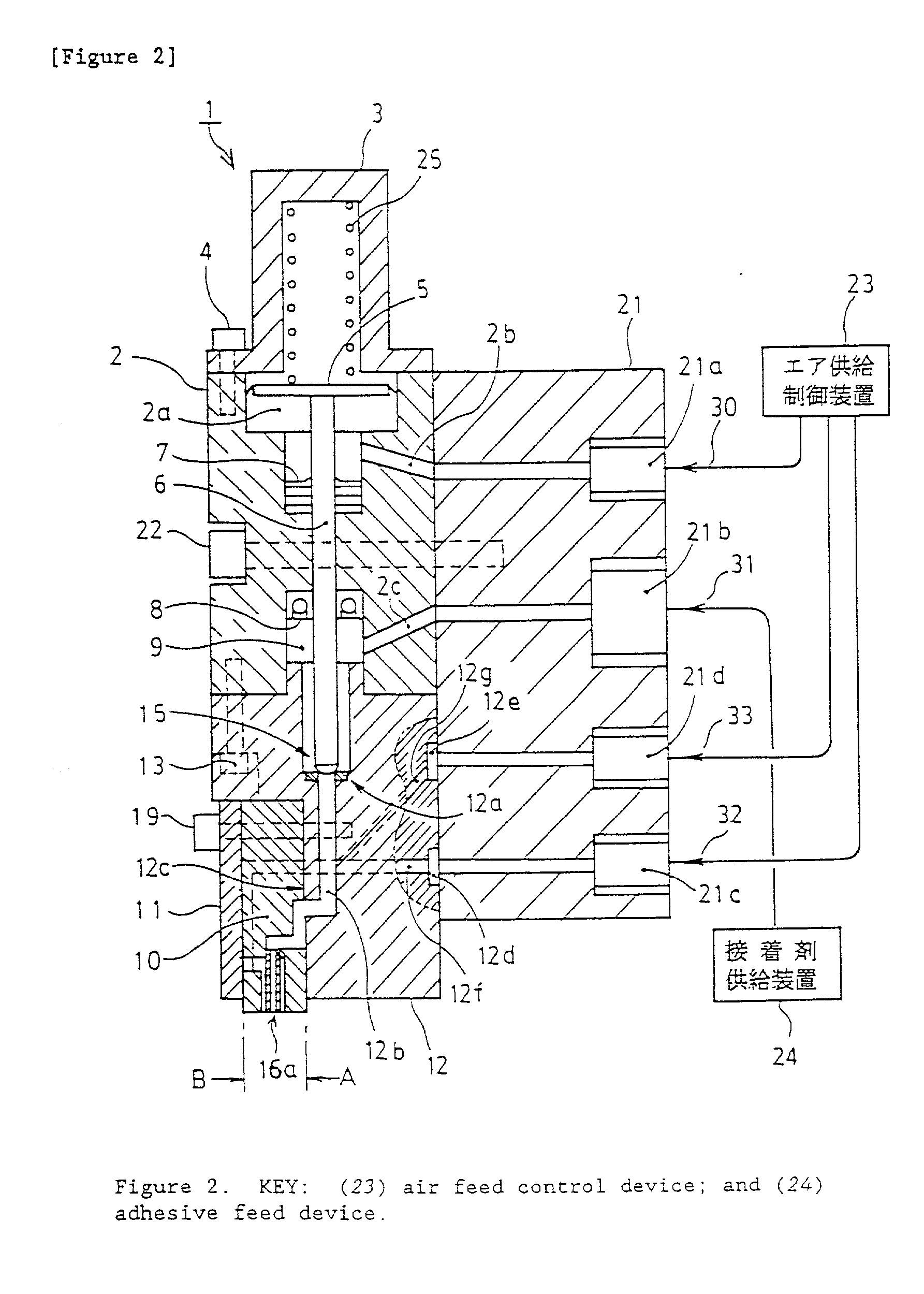
[0040] The above operations are performed while jetting cleaning air intermittently or continuously from the cleaning air jets provided adjacent to the front side and rear side of the adhesive discharge nozzle, thereby enabling continuous operation. In other words, the problem of airborne fibrous particles adhering to the nozzle holes, piling up and solidifying with the passage of time is avoided. This can prevent destabilizing the coating process and obstructing the extrusion of the adhesive. Furthermore, when the cleaning air is jetted continuously, irregular swings of the adhesive can be prevented, and a rectifying or stabilizing effect such as to make the bead-form adhesive swing regularly in the right and left directions is achieved.
[0041] It is desirable to adjust the discharge pressure of the cleaning air to a pressure lower than the discharge pressure of the pattern air during the extrusion of the adhesive. However, the discharge pressure of the cleaning air can be raised while the valve mechanism is closed, i.e., the extrusion of the adhesive is stopped, and thereby the adhesion of dust is prevented more effectively.
[0054] The jetting of cleaning air 33 prevents fine fibrous dust floating in the air from sticking around the adhesive discharge nozzles 16a, and enables stable application of the adhesive for long periods of time. This cleaning air jetting may be continuous or intermittent. If the cleaning air is jetted continuously, a rectifying effect such as to make the bead-form adhesive swing regularly in the right and left directions by preventing irregular swings of the adhesive is also achieved. Furthermore, it is desirable to adjust the discharge pressure of the cleaning air to a pressure lower than the discharge pressure of the pattern air. The discharge pressure of the cleaning air can be raised while the valve mechanism is closed, i.e., the extrusion of the adhesive is stopped, and thereby the adhesion of dust is prevented more effectively. Moreover, according to test results, it is desirable to adjust the distance H from the leading end of the adhesive discharge nozzle 16a to the strand material 14 to 5-20 millimeters.
[0055] To stop the discharge of the adhesive, the operating air 30 being fed to the underside of the piston 5 is released by the operation of the air feed control device 23, then the piston 5 and the valve stem 6 move downward by the force of the spring 25, and the valve mechanism 15 closes and the dis-charge of the adhesive stops. Thus, the open and shut operation of the valve mechanism 15 can achieve intermittent application of the adhesive.

Problems solved by technology

Also, in a process of this kind, the materials to be coated with the adhesive are not always elastic members, there are cases where strand materials with no stretching properties are coated with the adhesive and bonded to a substrate.
The first aforementioned adhesive coating device is known to have the following problems.
If the thickness or shape of the strand material changes, the size of the inverted V-shape groove also must be changed, and this leads to troublesome operation and extra time.
As a result, the strand material can be severed, or the grooves of the nozzle member can wear during lengthy operation and become larger than the diameter of the strand material.
Furthermore, although the adhesive is applied sufficiently to the area facing the nozzle hole of the strand material, the adhesive is not applied sufficiently to the opposite underside, and this can result in poor adhesion.
Moreover, because fiber products are being transferred at high speed, the operating environment is such that fine fibrous dust is more easily formed by friction between the fiber products and mechanical devices.
This fine airborne dust adheres readily to the nozzle hole sections, and this adhered dust piles up over time, solidifies, and destabilizes the coating process.
Yet another problem has been that, when applying the adhesive intermittently by controlling the opening and closing of the valve mechanism, the adhesive remaining downstream from the valve mechanism is inevitably drawn out by the strand material even after the valve mechanism is closed, and a poor final coating results.
In the second known device mentioned above, the spiral pattern is sometimes difficult to control across the length of the strand material.
This can lead to uneven or nonuniform application of the spiral bead of adhesive to the strand material.

Method used

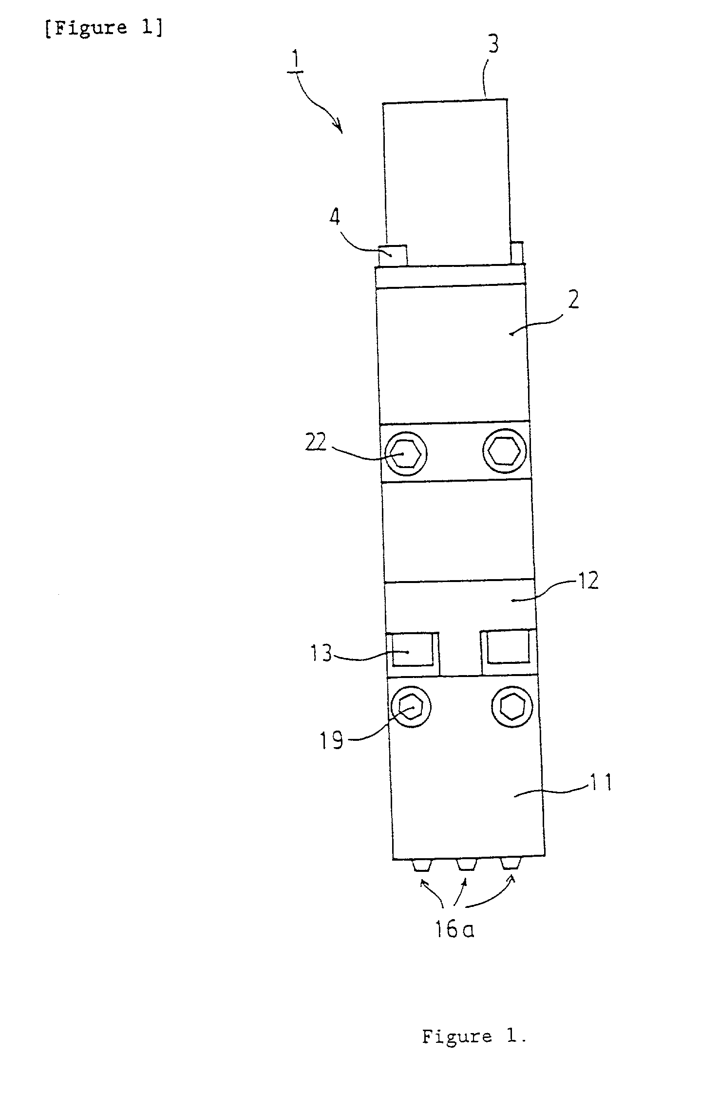

Image

  • Device and method for applying adhesive to materials such as strands
  • Device and method for applying adhesive to materials such as strands
  • Device and method for applying adhesive to materials such as strands

Examples


Embodiment Construction

[0056] Many tests of applying an adhesive to a strand material were repeated under the following conditions, and good results were obtained in all the tests. The conditions were as follows:

[0057] (1) strand material used as the substrate: strand elastic, thickness 560 denier (diameter about 0.28 mm), traveling speed 150-170 m / minute.

[0058] (2) Type of adhesive used: product No. H-6830 from Nitta Findley Co., Ltd. and product No. HE-1 from Japan N.S.C. Co., Ltd., both being rubber-based hot-melt adhesives.

[0059] (3) Melting temperature of adhesive upon heating: 150.degree. C. for H-6830 and 160.degree. C. for HE-1.

[0060] (4) Distance from the leading end of the adhesive discharge nozzle to the workpiece: 5-20 mm.

[0061] (5) Diameter of the adhesive discharge nozzle: 0.6 mm.

[0062] (6) Discharge pressure of the adhesive: 7-14 kg / cm.sup.2.

[0063] (7) Diameter of pattern air jet nozzle: two diameters, 0.46 mm and 0.50 mm.

[0064] (8) Pressure of pattern air: 0.3-1.0 kg / cm.sup.2.

[0065] (9) Ar...


PUM


Abstract

A device and method for applying adhesive to materials, such as elastic strands, used in the production of nonwoven products. Generally, a nozzle is provided and includes a liquid discharge orifice configured to discharge a bead of liquid adhesive. First and second pattern air discharge orifices are associated with the first liquid discharge orifice to vacillate or oscillate the adhesive bead. First and second cleaning and stabilizing air discharge orifices are also associated with the first liquid discharge orifice. These latter air discharge orifices keep airborne contaminants away from the associated liquid discharge orifice and also stabilize the oscillation of the adhesive bead in a single plane. A method in accordance with the invention includes using the nozzle to dispense a vacillating bead of adhesive onto a strand of material.

Description

[0001] This application claims the priority of Japanese Patent Application No. 2000-117263 filed Mar. 14, 2000, the disclosure of which is hereby fully incorporated by reference herein.[0002] The present invention pertains to a device and a method for applying an adhesive to materials such as strands, which are used by subsequently bonding them to a substrate.[0003] The structure of a disposable diaper is disclosed, for example, in Japanese Patent Kokai No. 11[1999]-285,510. In the structure of this disposable diaper an elastic strand(s) is provided at various locations including at the bending section and free ends of a sheet so as to form a barrier. In the process of producing disposable diapers with this kind of structure, the disposable diapers are produced through steps such as applying an adhesive to elastic strand material being fed continuously, then bonding the elastic strand material to a base or substrate material which forms the main part of the diaper and which is also ...

Claims


Application Information

Patent Timeline
Patent Type & Authority Applications(United States)
IPC IPC(8): A61F13/15B05D1/40B05B7/06B05B7/08B05C5/00B05C5/02B05C9/04B05D7/20
CPCA61F13/15593B05B7/0861B05C5/0241
Inventor NAKAMURA, YUKIO
Owner NORDSON CORP
Learn More