Method and apparatus for measuring spectral irradiance distribution

a technology of spectral irradiance and method, applied in the direction of optical radiation measurement, instruments, spectrometry/spectrophotometry/monochromators, etc., can solve the problems of complicated conventional apparatuses, and complicated indoor light sources, and achieve simple apparatus construction, simple construction, and easy calculation of spectral irradiance distribution.

Inactive Publication Date: 2001-09-27
FUJITSU LTD
View PDF0 Cites 10 Cited by
  • Summary
  • Abstract
  • Description
  • Claims
  • Application Information

AI Technical Summary

Benefits of technology

[0022] In order to attain the above first-named object, according to a first generic feature of the present invention, there is provided a method of measuring a spectral irradiance distribution of light, comprising the steps of: receiving the light on s (natural number) optical sensors, which respectively have s kinds of given spectral sensitivities, via n (natural number) light-transit sections, which respectively have n kinds of given optical characteristic coefficients; detecting individual responses for the light (receiving irradiances of the light), which is received via the n light-transit sections, by each and every one of the s optical sensors, and obtaining (n.times.s) responses for the received light; and calculating m (natural number) spectral irradiances for m kinds of wavelengths as a spectral irradiance distribution of the light, based on one or more linear formulae established between the optical characteristic coefficients, the spectral sensitivities, the (n.times.s) receiving irradiances, and the spectral irradiance distribution of the light. With this method, it is possible to calculate a spectral irradiance distribution of light with ease and to make the apparatus simple in construction with the reduced number of the optical sensors.
[0039] As a still further preferable feature, the light-transit selection is a filter which allows the light to transmit therethrough; the optical characteristic coefficient is a spectral transmittance of the filter; and the receiving irradiance of the light transmitted through the filter is detected by the optical sensors. With this preferable feature, it is possible to make the apparatus simple in construction.

Problems solved by technology

However, such conventional apparatus has to be equipped with these photosensitive sensors having different optical sensitivities as many as the number of the wavelengths by which the measurement is performed.
As a result, the conventional apparatus is complicated and very expensive due to the increased number of the photosensitive sensors.
However, the above-mentioned conventional methods have the following problems:
Generally, indoor light sources are various types, many of which are complicated.
Therefore it is practically difficult that all types of indoor light sources are measured under the same restriction that a spectral irradiation distribution is measured within a range such as to be expressed by a linear combination of three components.
It is impossible to measure the spectral irradiance distribution of the light irradiating an object surface.
Accordingly, with either these two conventional methods, it is difficult to measure a spectral irradiance distribution of light irradiating an object surface without using any expensive measuring equipment.

Method used


Image

  • Method and apparatus for measuring spectral irradiance distribution
  • Method and apparatus for measuring spectral irradiance distribution
  • Method and apparatus for measuring spectral irradiance distribution

Examples


first embodiment

[0102] (B)

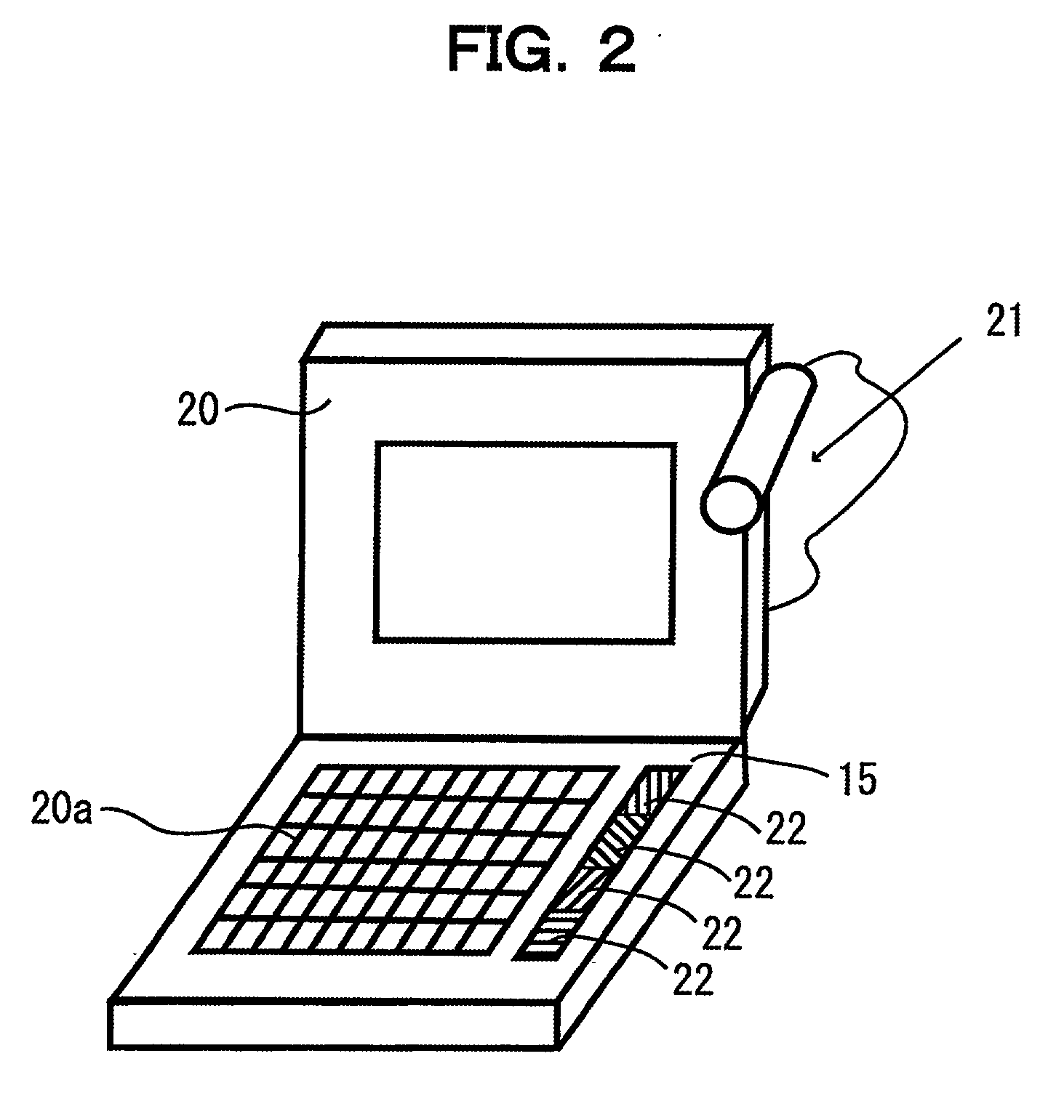
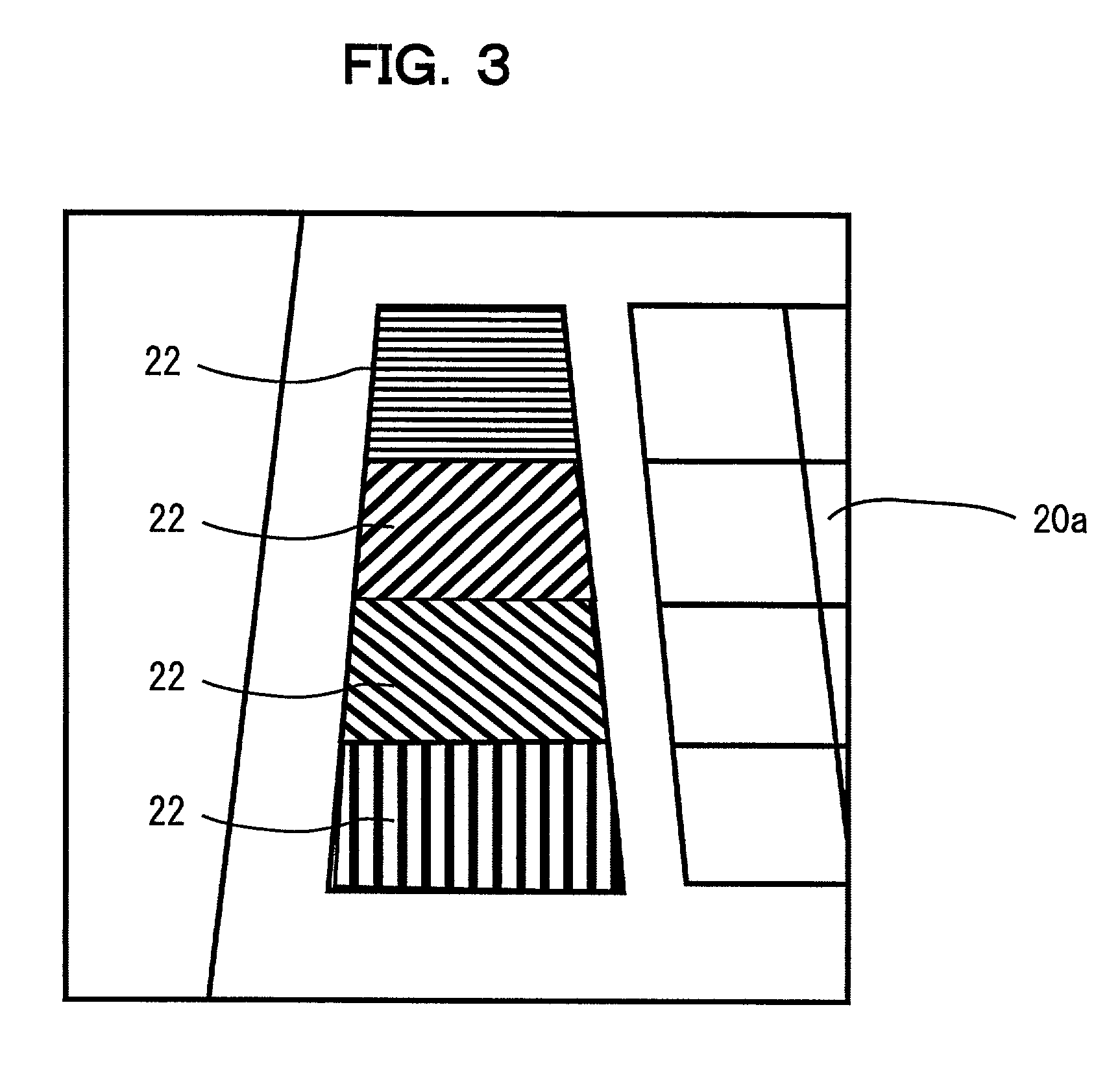
[0103] FIG. 2 is a diagram schematically showing a first embodiment to which the spectral irradiance distribution measuring apparatus is applied, and FIG. 3 is a diagram schematically showing an image photographed by a digital camera. The apparatus of FIG. 2 uses a notebook type computer and a digital camera in combination. Namely, the apparatus is equipped with a notebook type computer 20, a digital camera (optical sensor) 21, and four color chips (light-transit sections) 22, which respectively correspond to the reflectors 14.

[0104] The plural (four in FIG. 2) color chips 22, which correspond to the reflectors 14, are disposed side by side on an object surface 15 where a keyboard 20a of the notebook type computer 20 is installed. The four color chips 22 respectively have different reflectances (optical characteristic coefficients), which are given beforehand. The reflectavances of the individual color chips 22 are preferred to be largely different from one other, and the ...

second embodiment

[0154] (C)

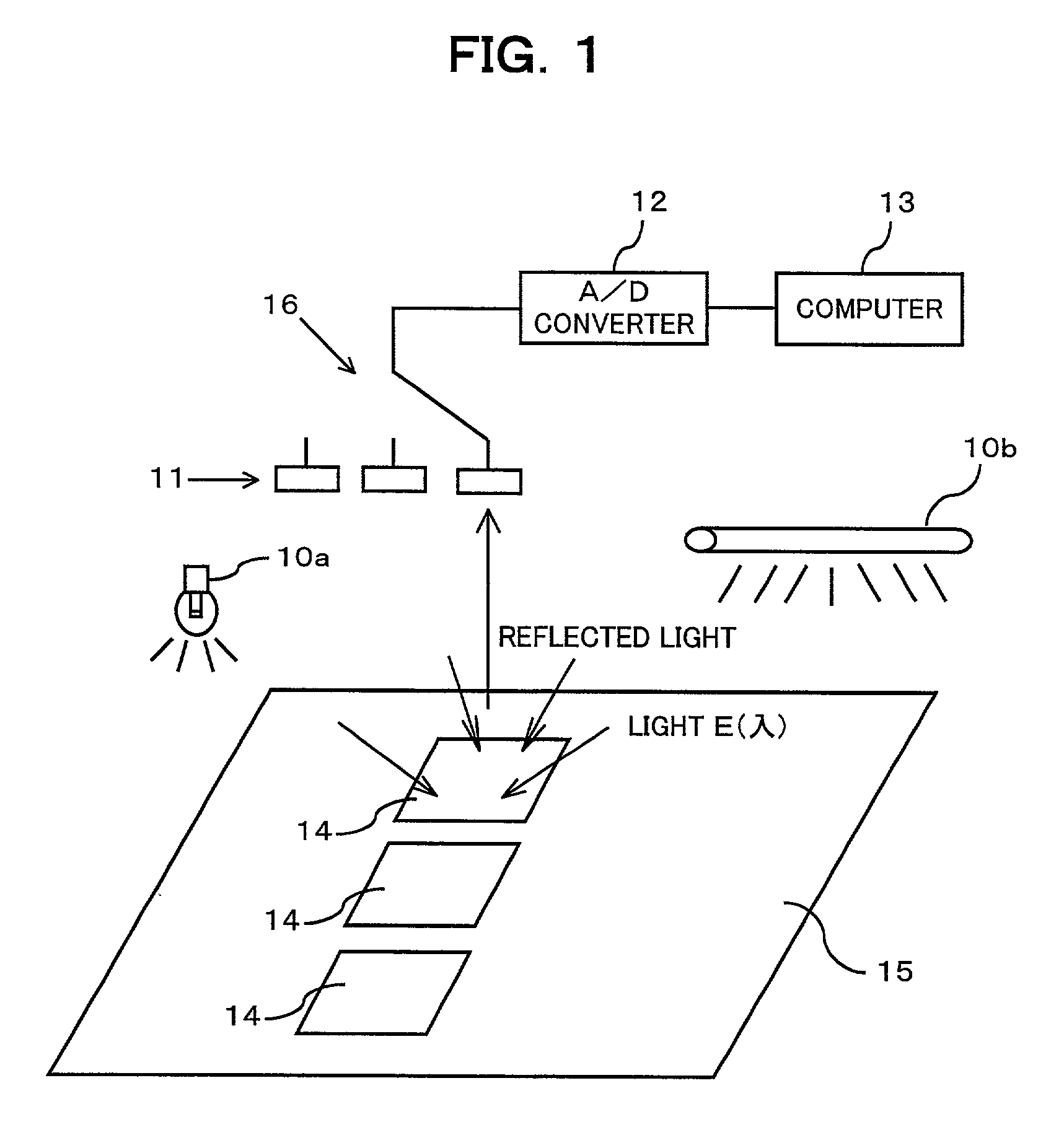
[0155] FIG. 8 is a diagram schematically showing an apparatus for measuring a spectral irradiance distribution according to a second embodiment of the present invention. The apparatus of FIG. 8 includes scattering filters 14' as substitutions for the reflectors 14 of FIG. 1. Like reference numbers designate similar parts or elements throughout FIG. 1 and FIG. 8, so any repetitious explanation is omitted here.

[0156] The n (n is a natural number, e.g., 3 in FIG. 8) scattering filters 14', which respectively have n kinds of given transmittances T(.lambda.) (optical characteristic coefficients), are illuminated by the light to be measured. The n scattering filters 14' is disposed on the object surface 15.

[0157] The s (s is a natural number, e.g., 3 in FIG. 8) optical sensors 11, which respectively have s kinds of given spectral sensitivities S(.lambda.) (optical characteristic coefficients), detect individual receiving irradiances of the light received via the n scattering fil...


PUM


Abstract

In measuring a spectral irradiance distribution of light, light is irradiated to n (natural number) light-transit sections, which respectively have n kinds of given optical characteristic coefficients, and s (natural number) optical sensors, which respectively have s kinds of given spectral sensitivities, receive the light via the n light-transit sections and detects individual responses for the received light. Then a calculating section calculates m (natural number) spectral irradiances for m kinds of wavelengths as a spectral irradiance distribution based on linear formulae established between the optical characteristic coefficients, the spectral sensitivities, (n.times.s) responses for the light obtained by the s optical sensors, and the spectral irradiance distribution of the light.

Description

BACKGROUND OF THE INVENTION[0001] 1. Field of the Invention[0002] The present invention relates to a method and an apparatus which are suitable for use in measuring a spectral irradiance distribution.[0003] 2. Description of the Related Art[0004] When a computer, such as a personal computer (PC, hereinafter also called the computer) processes a color image, such as editing a color image captured into the computer using a scanner while checking the color image displayed on the monitor, or printing a color image using a color printer, colors of an object for processing have to be accurately calculated by the computer.[0005] Generally, the basic colors of an object are expressed in the form of tristimulas XYZ values of the light reflected from the object (Gutnter Wyszecki and W. S. Stiles, "Color Science: Concepts and Methods, Quantitative Data and Formulae Second Edition, 3.3.8 Calculation of CIE Tristimulus Values and Chromaticity Coordinates", John Wiley & Sons, Inc. (1982)). Accura...

Claims


Application Information

Patent Timeline
IPC IPC(8): G01J3/52G01J3/28G01J3/36G01J3/46G01J3/50G01J3/51
CPCG01J3/28G01J3/36G01J3/462G01J3/50G01J2003/467
Inventor SHIMIZU, MASAYOSHIMORI, MASAHIROSUZUKI, SHOJI
Owner FUJITSU LTD
Why Eureka
Try Eureka