
SPR sensor system

a sensor and sensor finger technology, applied in the direction of material testing goods, instruments, analysis by subjecting materials to chemical reactions, etc., can solve the problems of high sample consumption, high cost of sensor fingers and their sensitiveness to physical contact, and the need for homogeneous surfaces on the surfa

Inactive Publication Date: 2001-10-04
GRAFFINITY PHARMA DESIGN
View PDF9 Cites 50 Cited by
  • Summary
  • Abstract
  • Description
  • Claims
  • Application Information

AI Technical Summary

Benefits of technology

[0018] Preferably the separating means assure in addition that no contamination between the sensor fields or SPR sensor surface areas can occur. This is achieved by the separating means forming elevations above the SPR sensor surface areas in the direction perpendicular to the substrate preferably 0.01 mm to 5 mm differing in height. It is good practice when the flanks or surfaces of the separating means forming vessels for receiving a sample fluid are hydrophobic or hydrophobicized so that an aqueous solution is well contained without the possibility of cross-contamination with other SPR sensor surface areas.
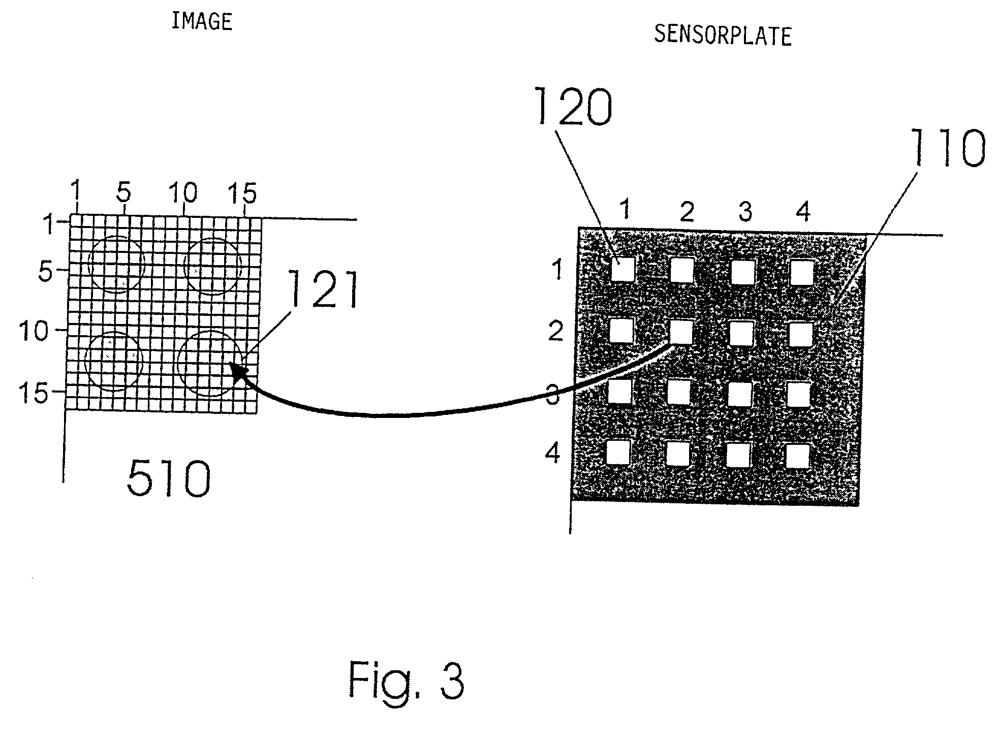
[0074] Due to the possibly of creating minute sensor surface areas and also due to it being possible to precisely calibrate or identify the sensor surface areas in spatial resolution imaging the array can be configured so that only a small number of pixels, namely less than 10, preferably five or less, is assigned to each sensor field in imaging.

Problems solved by technology

The disadvantage is the expense in producing the sensor fingers and their sensitiveness to physical contact as well as the relatively high sample consumption in coating.
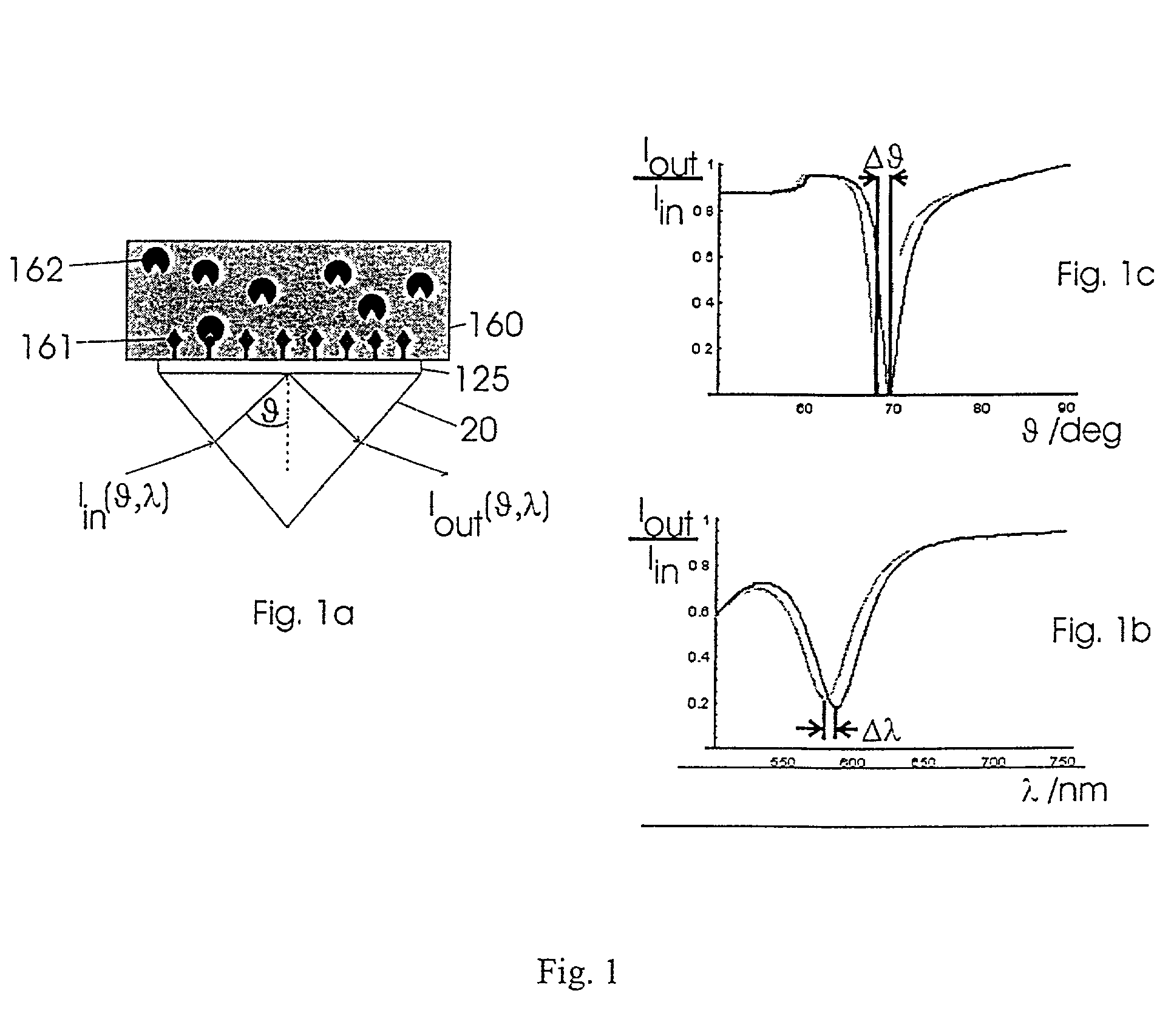
The disadvantage here is that the surfaces need to be very homogenous since it is only the region of the sensor surface area that shows a contrast in imaging under SPR conditions that exhibits the same layer thicknesses.
Also a disadvantage in this system is the relatively large pixel region to which a DNA square needs to be assigned on the CCD camera to ensure adequate contrast.
These requirements conflict with the need for a miniaturized SPR sensor array for universal application.
The disadvantage in this case is that making use of a throughflow system makes it difficult to use and miniaturize a two-dimensional sample array (two-dimensional array).

Method used


Image

  • SPR sensor system
  • SPR sensor system
  • SPR sensor system

Examples


Embodiment Construction

[0075] FIG. 9a shows a detail (200.times.150 pixels) of an image of a sensor plate having a matrix of 562.5.times.1125 .mu.m.sup.2, as obtained with an optical assembly as described in the last paragraph. The size of the square sensor fields is 280.times.280 .mu.m.sup.2. With these dimensions approx. 12,000 sensor fields can be accommodated on the surface area of microtiter plate. Structuring the sensor plate was done with Ormocer to which graphite was admixed, the thickness of this layer being approx. 50 .mu.m. Imaging was done on a CCD chip 1024.times.1280 pixels large. As evident from the magnified view (FIG. 9b) a sensor field of roughly 5 pixels was available for detecting the reflection spectrum.

[0076] Referring now to FIG. 10 in conclusion there is illustrated a spectrum obtained from 5 pixels, the transmission of the monochromator still being superposed in this case. The quality of these spectra indicates an accuracy of 2 10.sup.-4 for detecting changes in the refractive ind...


PUM


Abstract

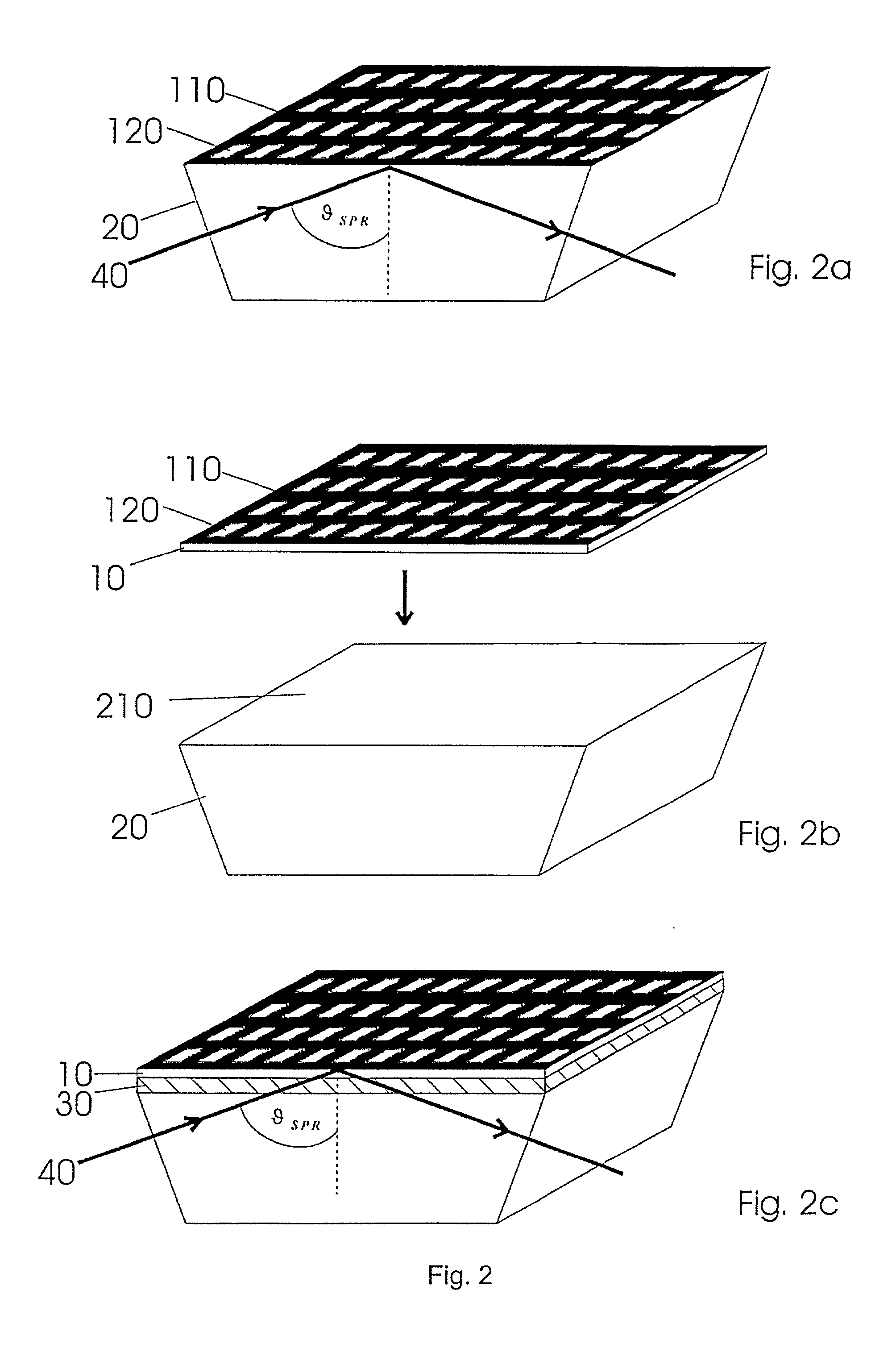
The invention relates to an SPR sensor array comprising a plurality of SPR sensor surface areas (120) arranged on a substrate (10, 20) in a two-dimensional matrix located in a plane to which the SPR sensor surface areas (120) are parallel and whereby radiation capable of exciting surface plasmons in the SPR sensor surface areas (120) under specific physical conditions can be guided through the substrate (10, 20) to be reflected from the SPR sensor surface areas, as well as separating means (110) for separating each SPR sensor surface area (120) from its neighboring SPR sensor surface area (120), wherein the separating means (110) and SPR sensor surface areas (120) are provided such that at least outside of surface plasmon resonance occurring in the SPR sensor surface areas (120) the radiation (40) guided through the substrate (10, 20) is reflected in the region of the separating means to a different degree than in the region of the SPR sensor surface areas (120) to create a contrast between the separating means (110) and the SPR sensor surface areas (120) at least outside of surface plasmon resonance occurring in the SPR sensor surface areas (120) in the radiation reflected by the SPR sensor surface areas (120) and the separating means (110).

Description

[0001] The present invention relates to providing a SPR sensor array capable of simultaneously sensing a plurality of samples, to methods for its production, measurement assemblies as well as to adjustment and measurement methods for parallel readout of the sensor system and to use thereof in the search for active substances and in high-throughput screening.[0002] One modern approach in the search for active substances involves generating a large number of diverse chemical compounds by means of automated synthesizers, this plurality of diverse structures then being tested for binding to interaction partners often represented by biomacromolecules such as proteins. One automated method which assays a large number of samples in this way is also termed high-throughput screening.[0003] Due to the biological dispersion of the results in studying the bindings it is particularly important to achieve exactly the same conditions for all compounds in the binding test. This is why the test idea...

Claims


Application Information

Patent Timeline
IPC IPC(8): G01N21/55G01N21/27
CPCG01N21/253G01N21/553
Inventor DICKOPF, STEFANSCHMIDT, KRISTINAVETTER, DIRKBURKERT, KLAUS
Owner GRAFFINITY PHARMA DESIGN
Learn More