
Virtual image display apparatus and electronic equipment using thereof

a technology of virtual image display and electronic equipment, which is applied in the direction of television systems, identification means, instruments, etc., can solve the problems of increasing power consumption, hardly having the possibility of miniaturization follow-up, and increasing the size of the structur

Inactive Publication Date: 2001-10-04
PANASONIC CORP
View PDF11 Cites 31 Cited by
  • Summary
  • Abstract
  • Description
  • Claims
  • Application Information

AI Technical Summary

Problems solved by technology

Display means which utilizes liquid crystal or the like and which occupies a substantial part of the operating surface of an equipment has been prosperously used as such an image displaying means, but it can hardly have a possibility of follow-up of miniaturization of the equipment.
However, it has been raised such a problem that the structure becomes larger in the direction of the optical axis of the optical system.
Further, the higher the brightness of the image, the larger the power for the illumination, the power consumption is increased, and accordingly, the virtual image display unit becomes unsuitable for portable data terminals.

Method used


Image

  • Virtual image display apparatus and electronic equipment using thereof
  • Virtual image display apparatus and electronic equipment using thereof
  • Virtual image display apparatus and electronic equipment using thereof

Examples


first embodiment

[0045] (First Embodiment)

[0046] Explanation will be hereinbelow made of a first embodiment of the present invention with reference to the drawings. In this embodiment, a portable data terminal having a communication function is exemplified as an electronic equipment.

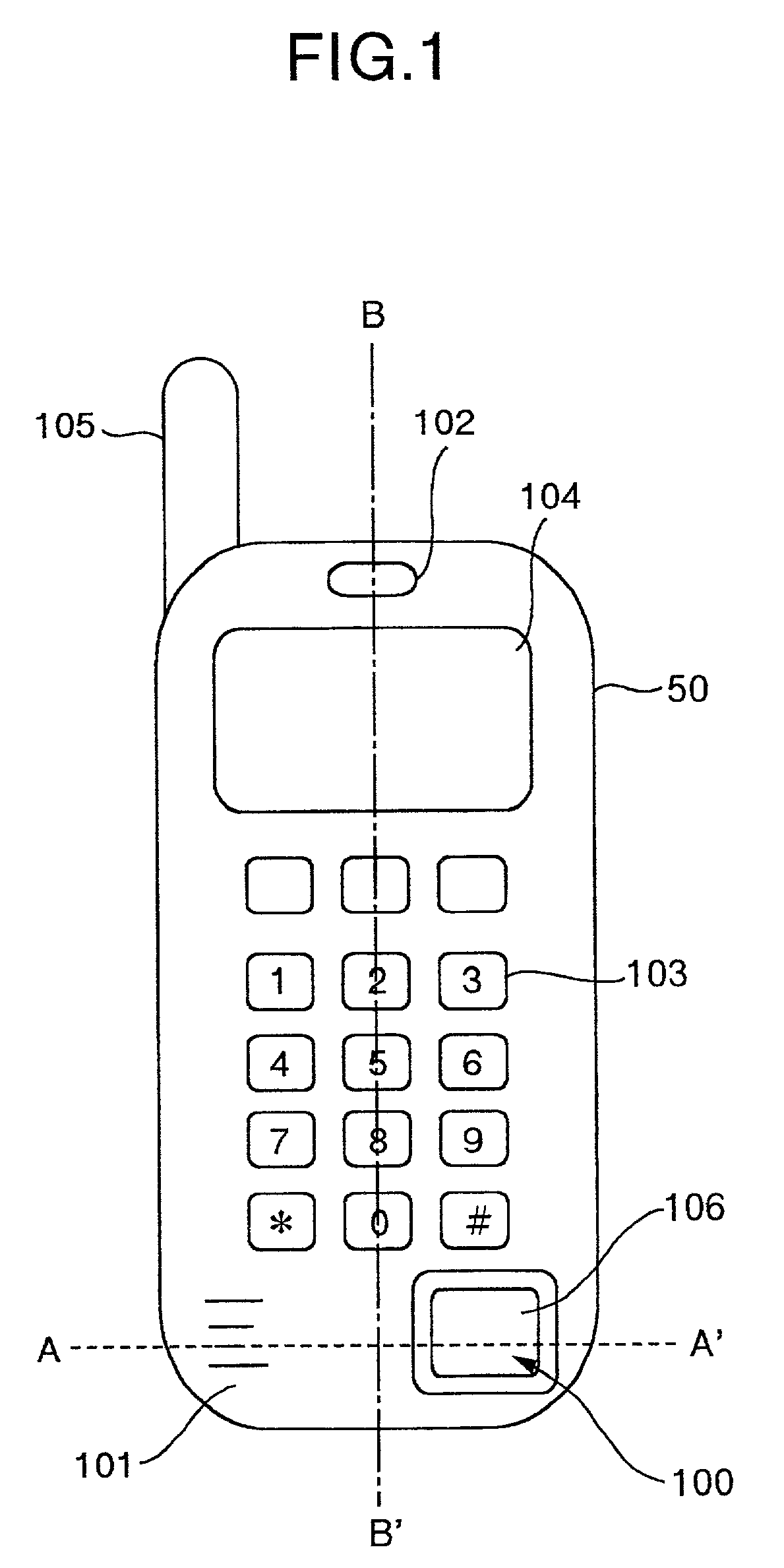
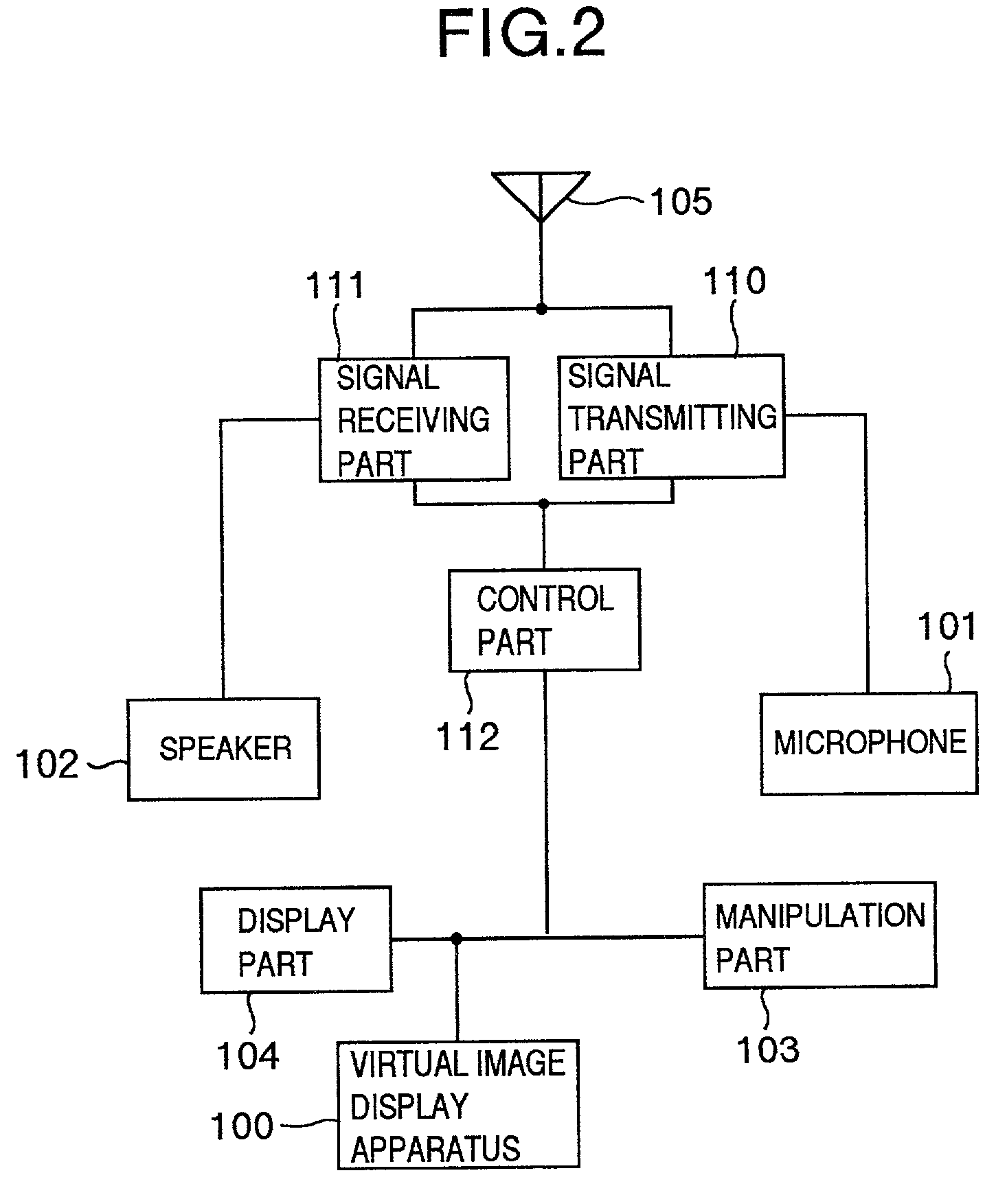
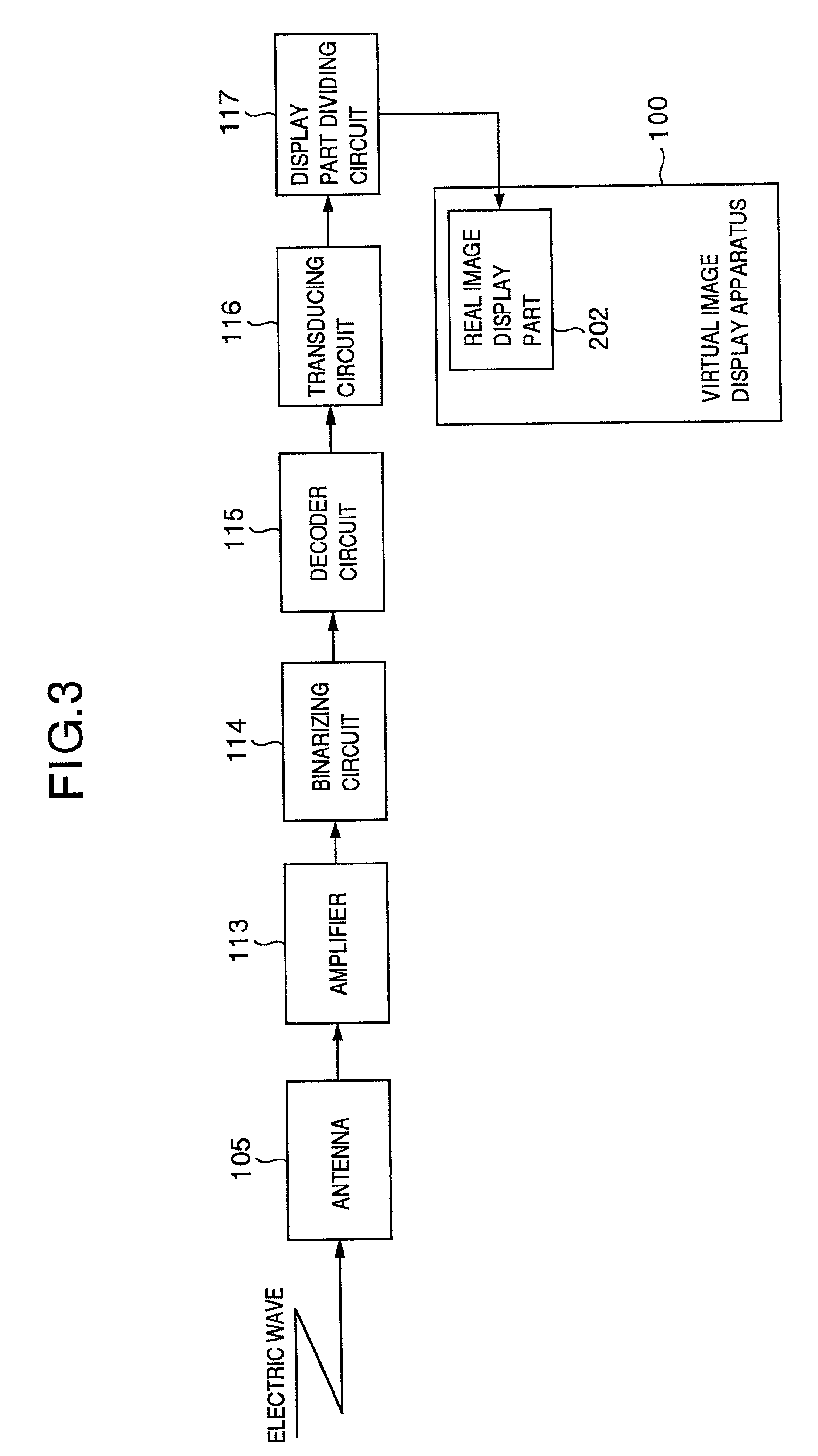
[0047] FIG. 1 is a front view illustrating a portable data terminal which is mounted thereon with a virtual image display apparatus in the first embodiment of the present invention, and FIG. 2 is a sectional view along line A-A' in FIG. 1. Further, FIG. 3 is a control block diagram illustrating a portable block diagram in the first embodiment of the present invention.

[0048] Referring to FIG. 1, there are shown the virtual image display apparatus 100 which is accommodated in a housing 50 of the portable data terminal and which will be detailed later, a microphone 101 for transducing voice into voice signals, a speaker 102 for transducing a voice signal into voice, a manipulation part 103 composed of dial buttons and the l...

second embodiment

[0089] (Second Embodiment)

[0090] Next, explanation will be made of a mode change of visual characteristics of the virtual image display apparatus with reference to the drawings. FIGS. 5a and 5b are schematic views illustrating the modes of visual characteristics of a virtual image display apparatus in another embodiment of the present invention, FIGS. 6a and 6b are schematic views illustrating display examples in the modes of visual characteristics shown in FIGS. 5a and 5b, FIG. 6a illustrating examples in the case shown in FIG. 5a while FIG. 6b illustrates examples in the case shown in FIG. 5b. FIGS. 5a and 5b show a condition in which the light guide member 300 is linearly developed into an optically equivalent form for the sake of convenience without directly showing the virtual image display apparatus 100 as it is.

[0091] Referring to these figure which schematically show the real image display part 202 and the light condensing member 400 having such a function that an image disp...

third embodiment

[0105] (Third Embodiment)

[0106] Next, explanation will be made of a mode change of visibility of the virtual image display apparatus in a third embodiment, with reference to the drawings. FIGS. 7a and 7b are schematic views illustrating the modes of visibility of a virtual image display apparatus in another embodiment of the present invention, FIGS. 8a and 8b are schematic views illustrating display examples in the modes of visibility shown in FIGS. 7a and 7b, FIG. 8a illustrating an example in the case shown in FIG. 7a while FIG. 8b illustrates an example in the case shown in FIG. 7b. It is noted that FIGS. 7a and 7b do not show the light guide member 300 for the sake of convenience.

[0107] Referring to FIGS. 7a and 7b which schematically show the real image display part 202 and the light condensing member 400 (which is composed of a single lens) having such a function that an image displayed on the real image display part 202 is magnified into a visual virtual image, explanation wi...


PUM

PropertyMeasurementUnit
thicknessaaaaaaaaaa
sizeaaaaaaaaaa
sizeaaaaaaaaaa

Abstract

There is provided a small-sized and lightweight image display apparatus which is thinned in the line of sight and which incorporates a display unit for displaying a magnified virtual image and a direct image, the display apparatus comprising a real image display part for displaying an image, an image magnifying means for optically magnifying the image formed in the real image forming means so as to form a virtual image, and a light guide means for guiding light from the real image display part to the image magnifying means, the magnifying means being formed in a triangular columnar shape having a substantially isosceles triangular cross-section, and having a first surface serving a light incident surface, a light emanating surface and a reflective surface, and a first internal reflecting surface and a second internal reflecting surface for reflecting light into the light guide means, wherein emanating light from the real image display part is incident upon the light guide means through the first surface, and is then reflected by the first internal reflection surface and the second internal reflection surface, and thereafter, the light emanating from the light guide means and entering into the image magnifying means.

Description

[0001] 1. Field Of The Invention[0002] The present invention relates to a virtual image display apparatus having a function of display of a magnified virtual image, for visually magnifying and displaying an image to be monitored, and also relates to an electronic equipment using thereof.[0003] 2. Description of Related Art[0004] These years, various information processing equipments, and in particular, equipments which can process visual information by means of liquid crystal or photoelectric image display means or the like, have been astonishingly progressed. The so-called mobile equipments, that is, data processing machines which can be personally used at any of various places, have also remarkably developed. The mobile equipments are desirable so as to have a compact body for portability, a high speed of data processing, several processing functions, and as well to have a means for precisely and straightforward displaying much more information to the user within a limited space o...

Claims


Application Information

Patent Timeline
Patent Type & Authority Applications(United States)
IPC IPC(8): G02F1/1335G02B27/02G03B21/14G09F9/00H04M1/02H04N5/64
CPCH04M1/0266
Inventor KIYOMATSU, SATOSHIOHTSUBO, KAZUMINAKASHIMA, KAZUYUKI
Owner PANASONIC CORP
Learn More