Intake air control device and internal combustion engine mounting the same

a control device and control device technology, applied in the direction of electric control, combustion-air/fuel-air treatment, machines/engines, etc., can solve the problems of insufficient consideration of vaporizing efficiency of heaters, insufficient consideration of fuel spraying to the intake pipe, and inability to stably supply sufficient vaporized fuel to each of the combustion chambers

Inactive Publication Date: 2001-10-11
HITACHI LTD +1
View PDF3 Cites 33 Cited by
  • Summary
  • Abstract
  • Description
  • Claims
  • Application Information

AI Technical Summary

Problems solved by technology

However, it is difficult that a fuel spray injected in the main intake air passage from the cold-start injector projecting inside the main intake air passage is sufficiently vaporized (atomized) and transported to each of combustion chambers by an intake air flowing the main intake air passage, and most of the fuel spray is adhered onto the inner surface of the main intake air passage to be stagnated.
Therefore, it is difficult to stably supply the sufficien

Method used


Image

  • Intake air control device and internal combustion engine mounting the same
  • Intake air control device and internal combustion engine mounting the same
  • Intake air control device and internal combustion engine mounting the same

Examples


first embodiment

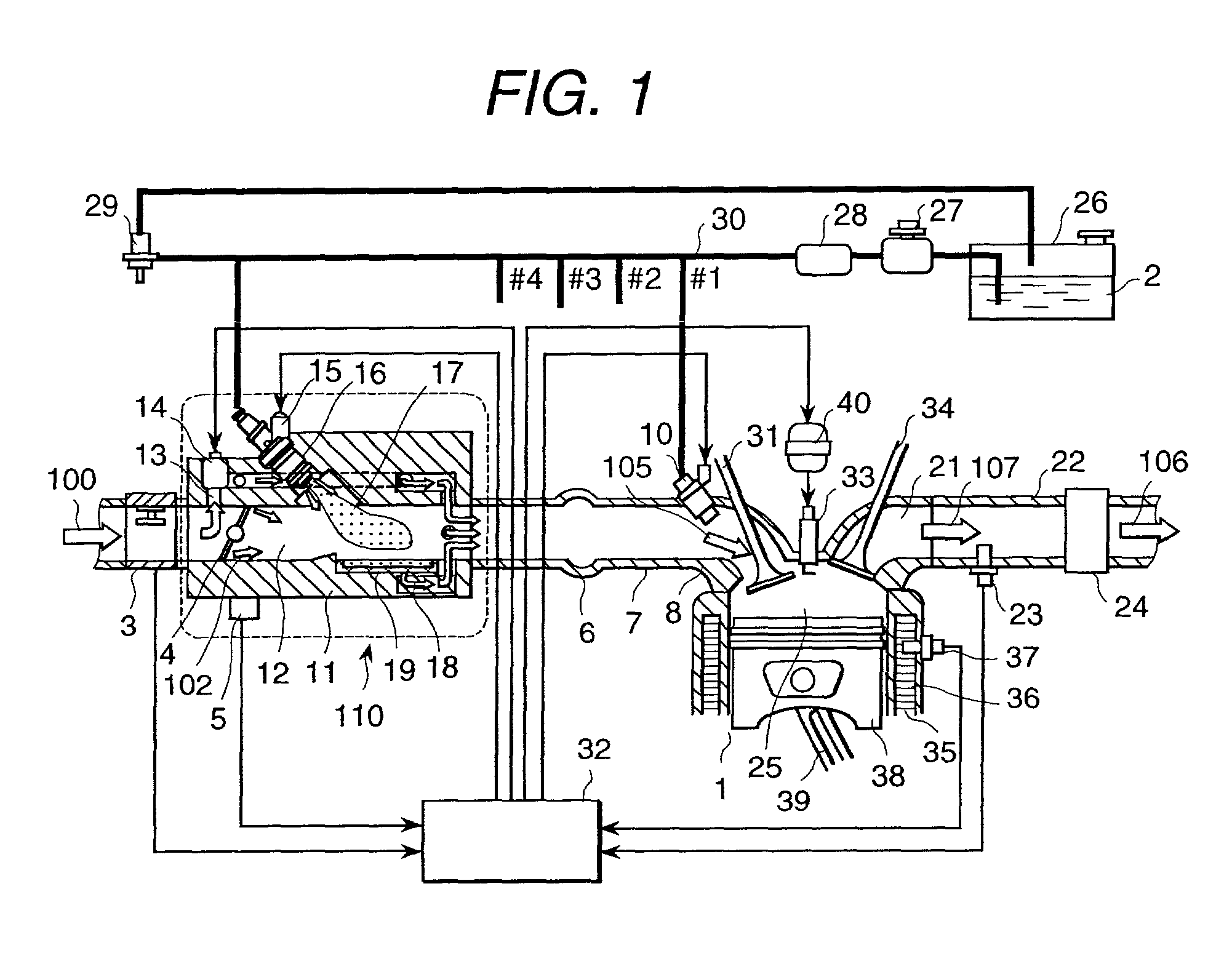
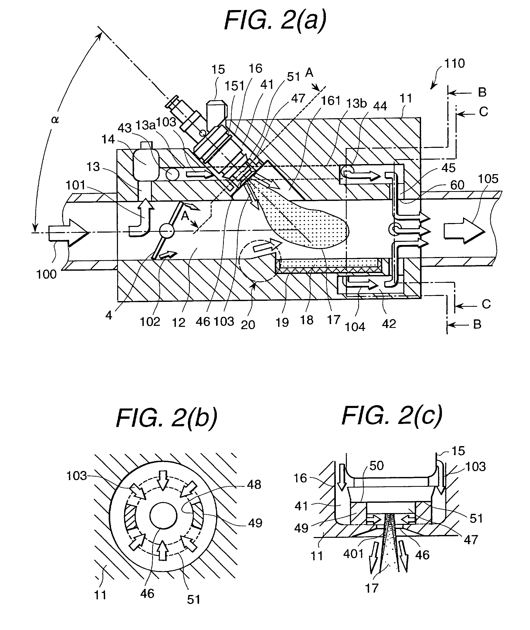
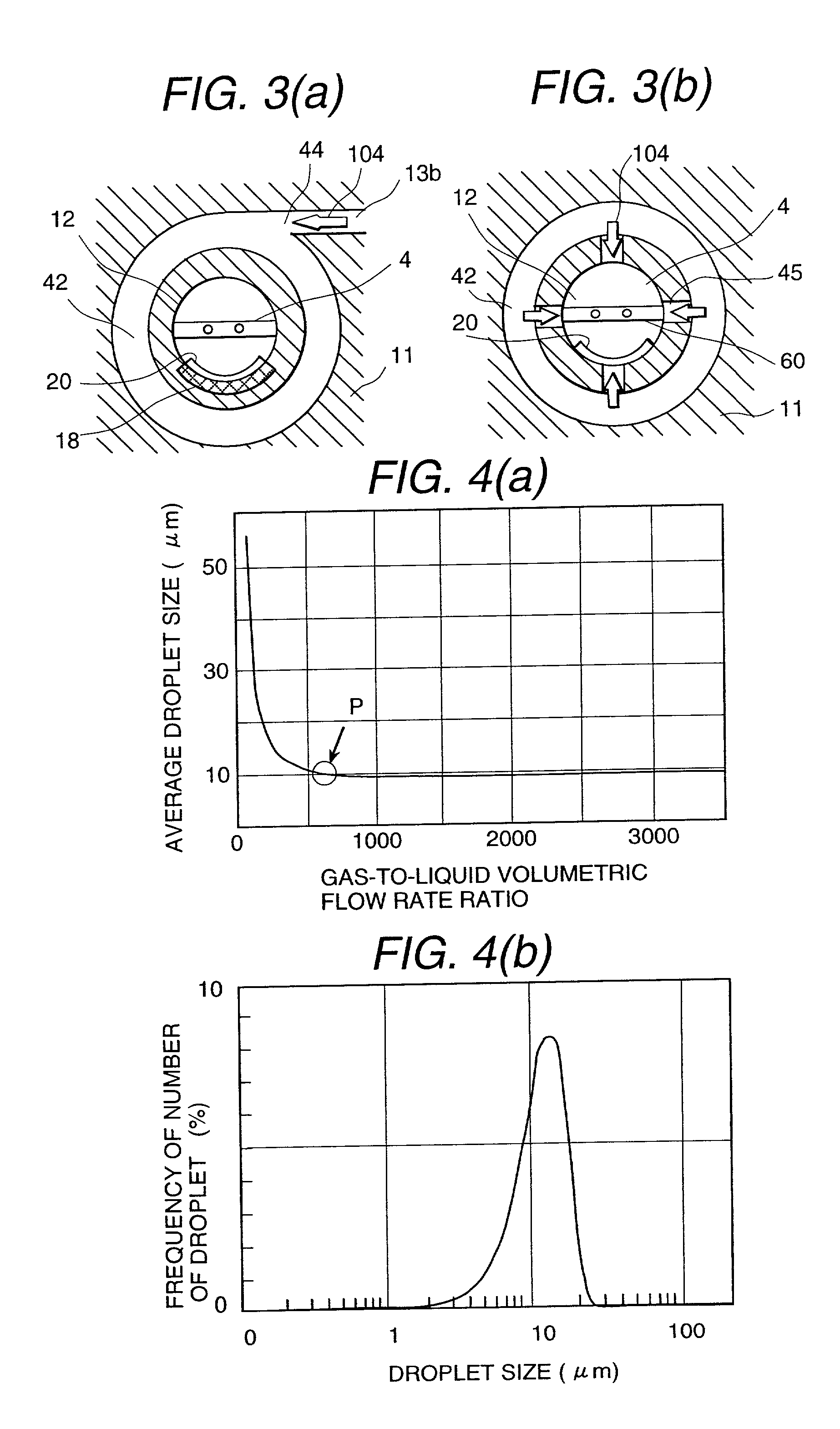
[0063] an intake air control device and an internal combustion engine mounting an intake air control device in accordance with the present invention will be described below, referring to FIG. 1 to FIG. 7.

[0064] Referring to FIG. 1, an internal combustion engine 1 is a well-known multi-cylinder internal engine of a spark ignition type using gasoline as the fuel, but only one of the cylinders is illustrated in the figure.

[0065] The intake air system, is composed of an air flow sensor 3 for measuring a flow rate of intake air 100 sucked through an air cleaner (not shown); an intake air control device 110 containing a throttle valve 4 of which opening-and-closing operation is linked to accelerator operation of a driver; a throttle valve positioning sensor 5 for measuring an opening degree of the throttle valve 4; an intake air assembly pipe 6; an intake air manifold 7 for branching the intake air assembly pipe 6 to each of the cylinders; and an intake air port 8 having an intake air val...

second embodiment

[0130] The second embodiment in accordance with the present invention will be described below, referring to FIG. 8.

[0131] A main different point of the second embodiment from the first embodiment shown in FIG. 2 is the construction of the bypass flow passage 13c through which the air for carrying the fuel spray flows, the other constructions are the same as those of the first embodiment. Therefore, the overlapped explanation will be omitted here.

[0132] In this embodiment, the bypass flow passage 13c branched at a branch inlet portion 43a is communicated with a branch outlet portion 60a formed in the body 11 so as to project in the main passage 12 between the throttle valve 4 and the depressed portion 161. The branch outlet portion 60a is opened toward the downstream side of the axial flow direction of the main passage 12. That is, the air 104 flowing out from the branch outlet portion 60a collides (merges) with the fuel spray 17 promoted in atomization in the depressed portion 161 b...

third embodiment

[0134] The third embodiment in accordance with the present invention will be described below, referring to FIG. 9.

[0135] A main different point of the third embodiment from the first embodiment shown in FIG. 2 is that instead of the throttle valve 4 operated linking to accelerator operation of a driver, an electronic control throttle valve (hereinafter, referred to as ETC) 52 for electrically controlling the opening degree is provided, and accordingly the ISC valve 14 is eliminated. When the ETC valve 52 is used, the amount of intake air at starting operation of the internal combustion engine 1 and during idling operation can be controlled without using the ISC valve 14. Therefore, the ISC valve 14 is unnecessary. Further, the construction of the carrier air passage 45a is changed as to be described later. The other constructions are the same as those of the first embodiment. Therefore, the overlapped explanation will be omitted here.

[0136] In this embodiment, the assembly pipe fuel...


PUM


Abstract

A main passage mounting a throttle valve and an air bypass flow passage for reducing HC emission by promoting atomization of the fuel spray injected from the assembly pipe fuel injector are integrated in a body of an intake air control device arranged upstream of an assembly pipe in one-piece structure to form a unit. Thereby, the intake air control device can be easily manufactured, and easily mounted on and dismounted from the intake air system. An amount of HC emitted at warming-up operation of an internal combustion engine is reduced by efficiently supplying fuel spray injected from an assembly pipe fuel injector at starting and warming-up operations to the internal combustion engine.

Description

[0001] 1. Technical Field[0002] The present invention relates to an intake air control device and an internal combustion engine mounting an intake air control device, and particularly to a technology improving combustion performance of an internal combustion engine and reducing an amount of hydrocarbon (hereinafter, referred to as HC) emitted at warming-up operation of the internal combustion engine.[0003] 2. Prior Art[0004] An intake air control device for an engine is disclosed in Japanese Patent Application Laid-Open Hei 4-232353. In the intake air control device, a cold-start injector projecting inside a main intake air passage is arranged at a position near an outer peripheral portion of a throttle valve when the throttle valve is in a partially open position.[0005] However, it is difficult that a fuel spray injected in the main intake air passage from the cold-start injector projecting inside the main intake air passage is sufficiently vaporized (atomized) and transported to e...

Claims


Application Information

Patent Timeline
IPC IPC(8): F02M31/135F02M35/10F02M69/04F02M69/30F02M69/32
CPCF02D41/3094F02M31/135F02M35/10019F02M35/10118F02M35/10177F02M35/10216F02M35/10268F02M35/1045F02M69/044F02M69/047F02M69/30F02M69/325F05C2201/021Y02T10/126Y02T10/42Y02T10/12Y02T10/40
Inventor AMOU, KIYOSHIOKAMOTO, YOSHIOKADOMUKAI, YUZOKOWATARI, TAKEHIKOMIYAJIMA, AYUMUNAGANO, MASAMIICHIHARA, TAKANOBUSAEKI, HIROAKISOMENO, TADASHI
Owner HITACHI LTD
Why Eureka
Try Eureka