Display panel module with improved bonding structure and method of forming the same

a technology of bonding structure and display panel, applied in the field of display panel modules, can solve the problems of critical relative displacement, short circuit, misalignment between,

Inactive Publication Date: 2001-10-25
VISTA PEAK VENTURES LLC
View PDF0 Cites 12 Cited by
  • Summary
  • Abstract
  • Description
  • Claims
  • Application Information

AI Technical Summary

Problems solved by technology

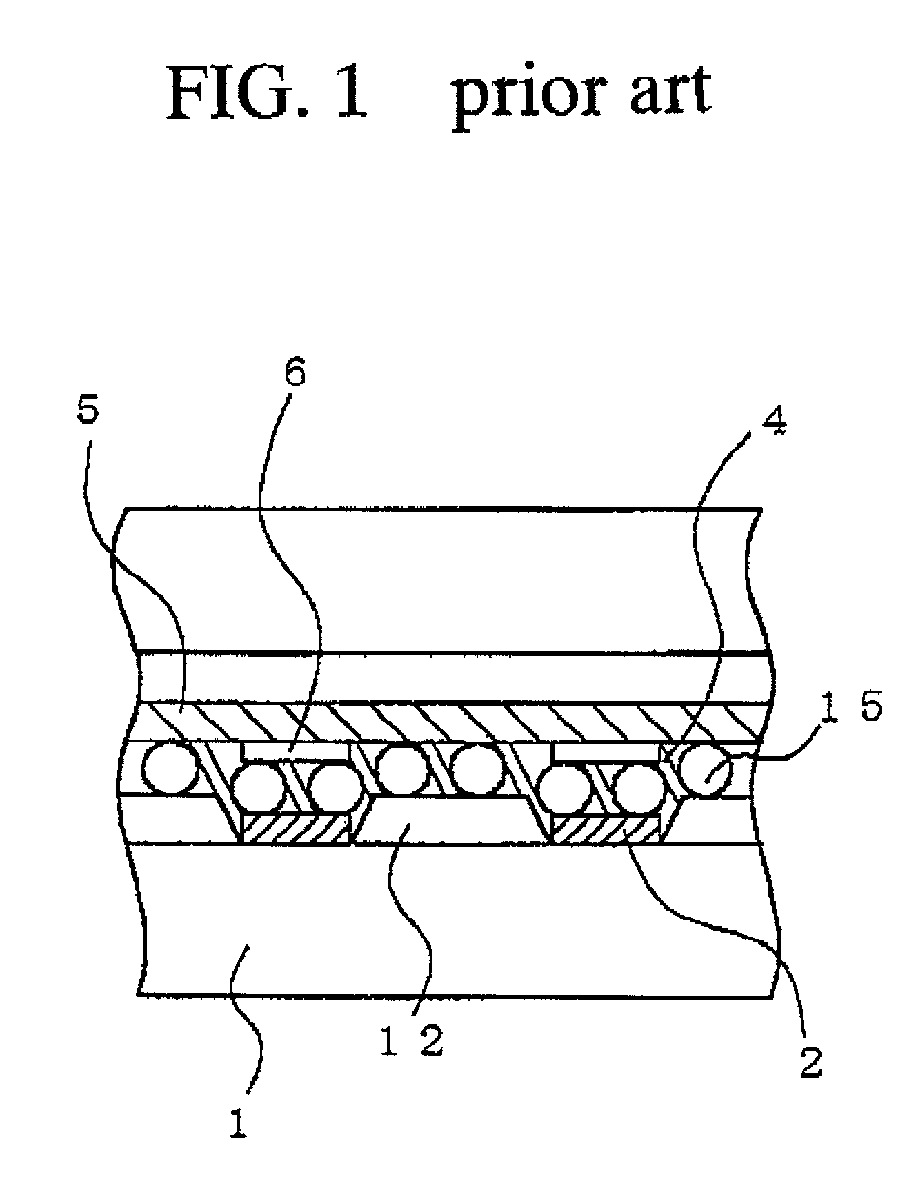
The thermal compression bonding process causes the substrate and the circuit board to show different thermal expansions, whereby the electrode terminals of the substrate and the lead terminals of the circuit board become different in pitch, resulting in a misalignment between them.
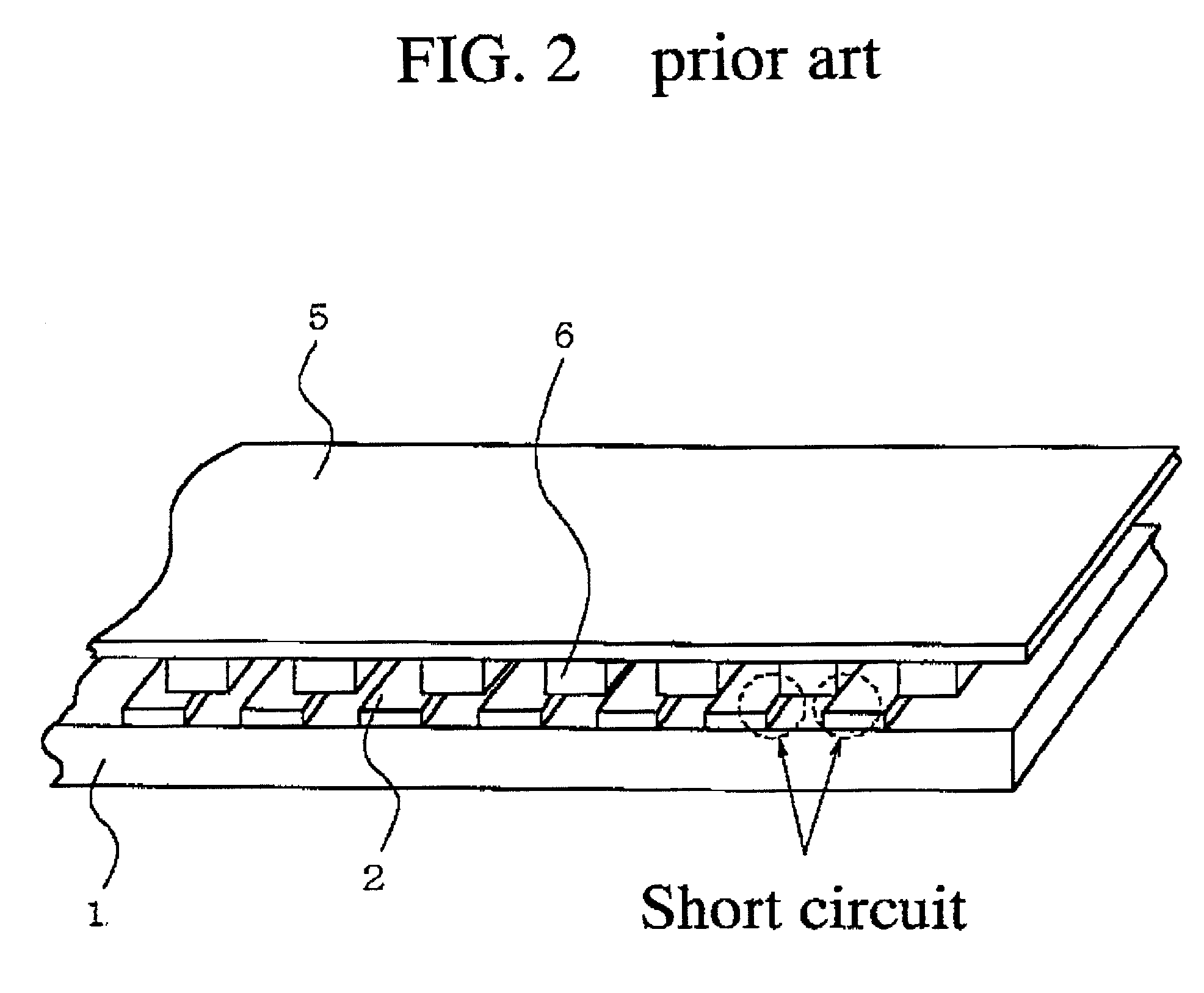
Narrowing the terminal pitch reduces such a critical relative displacement, which causes the short circuit.
The advanced ...

Method used


Image

  • Display panel module with improved bonding structure and method of forming the same
  • Display panel module with improved bonding structure and method of forming the same
  • Display panel module with improved bonding structure and method of forming the same

Examples


Embodiment Construction

[0065] A preferred embodiment according to the present invention will be described in detail with reference to the drawings. FIG. 4 is a fragmentary cross sectional elevation view of a display panel module with an improved bonding structure in a preferred embodiment of the present invention. FIG. 5 is a fragmentary perspective view of a supporting substrate to be bonded to a flexible printed circuit board through an anisotropically conductive film in the form of a display panel module of FIG. 4.

[0066] A display panel module has a supporting substrate 1 and a flexible printed circuit board 2. The supporting substrate 1 is transparent. The supporting substrate 1 has a thickness of 1.1 millimeters. Electrode terminals 2 are provided on a surface of the supporting substrate 1. The electrode terminals 2 are aligned at a constant pitch of 0.12 millimeters in a first direction which is parallel to a longitudinal direction of the supporting substrate 1 and the flexible printed circuit board...


PUM


Abstract

A display panel module comprises: a substrate; a circuit board; electrode terminals aligned in a first direction over a surface of the substrate, each of the electrode terminals extending in a second direction perpendicular to the first direction; lead terminals aligned in the first direction over a confronting surface of the circuit board to the substrate; at least an anisotropically conductive film sandwiched between the electrode terminals and the lead terminals; and a plurality of first electrically insulating walls provided on the substrate and positioned in at least selected plural ones of gaps between selected ones of the electrode terminals, and the selected ones of the electrode terminals being positioned on opposite side regions of the module, and the opposite side regions are distanced in the first direction and separated by a center region, wherein the first electrically insulating walls have a first height, which is higher than a first total height of the electrode terminals and the anisotropically conductive film.

Description

[0001] 1. Field of the Invention[0002] The present invention relates to a display panel module and a method of forming the same, and more particularly to a display panel module having an improved connection structure between a display panel and a circuit board and a method of forming the same.[0003] 2. Description of the Related Art[0004] Flat display panels of various types such as liquid crystal display panels, plasma display panels and electroluminescent display panels have been well-known to persons skilled in the above-described field. Such a display panel comprises an insulating substrate which has electrode terminals. The display panel forms a display panel module in combination with a flexible printed circuit board for driving the display panel. The display panel and the circuit board are electrically connected to each other through the following connection structure.[0005] The display panel has electrode terminals. The circuit board has lead terminals. The display panel and...

Claims


Application Information

Patent Timeline
IPC IPC(8): G02F1/1345G09F9/00H01J9/28H01J17/18H01J29/92H05K3/32H05K3/34H05K3/36
CPCH01J9/28H01J17/18H01J29/92H01J2211/46H01J2329/92H05K3/323H05K3/3452H05K3/361H05K2201/09909H05K2203/167H01J11/46
Inventor MIZUTANI, KAZUHIROKITAZUME, EIICHI
Owner VISTA PEAK VENTURES LLC
Why Eureka
Try Eureka