
Method and system for airborne meter communication

Inactive Publication Date: 2001-11-08
FOOTE CHARLES A
View PDF25 Cites 83 Cited by
  • Summary
  • Abstract
  • Description
  • Claims
  • Application Information

AI Technical Summary

Benefits of technology

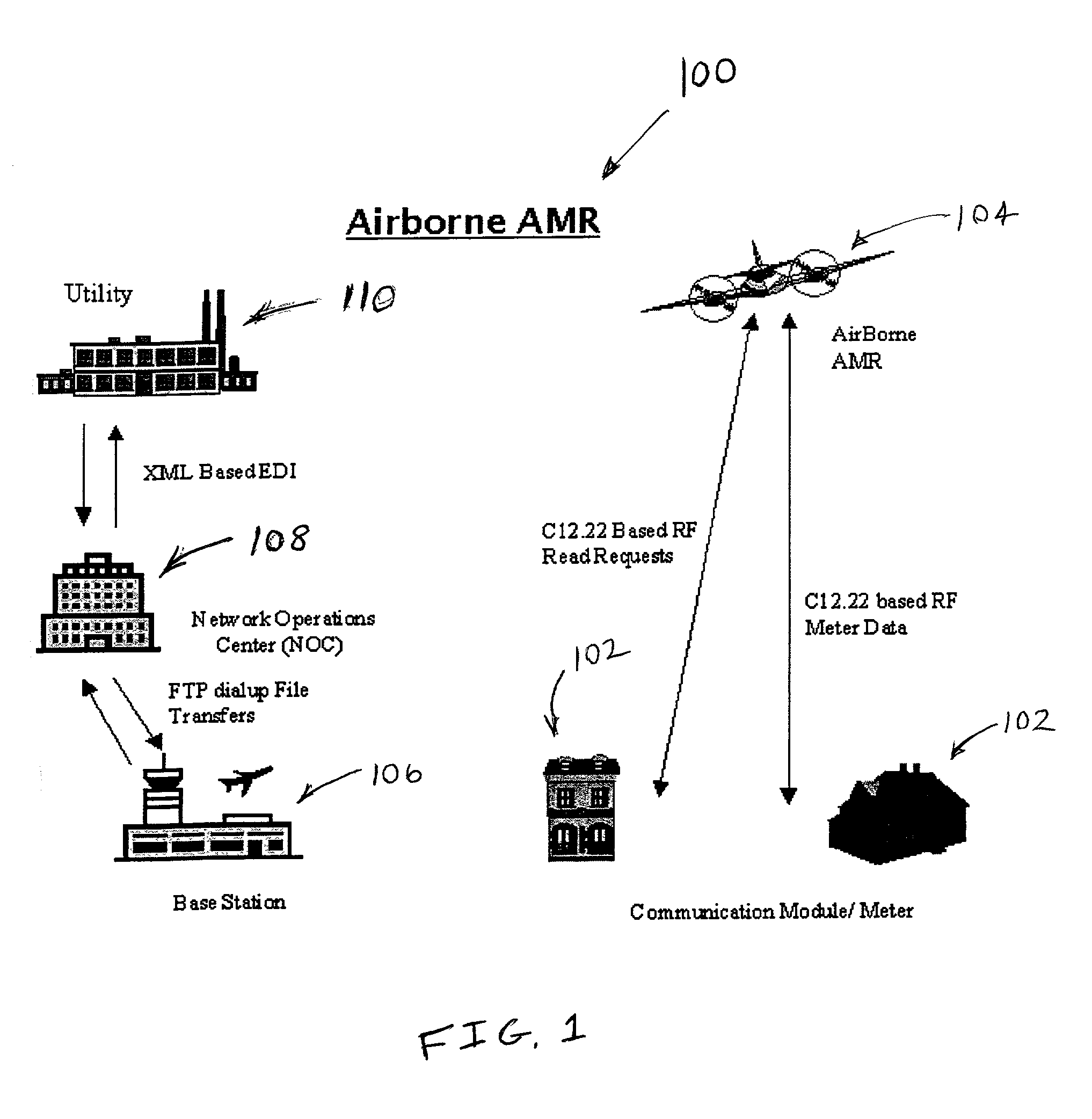
[0015] Yet another object of the invention is to provide an airborne meter communication system that can provide substantially real time communication between a ground based station and utility meters via an airborne platform.
[0022] The electronic meter reading system of the invention ensures extremely high accuracy in correctly associating the meter identification number and the meter location with virtually errorless power consumption data. The invention combines the electronic meter with cost effective mass produced commercial RF transceivers to provide an airborne based architecture to control a large population of meters and to command them to send their information when cued.
[0023] The invention may provide a cost efficient, accurate, timely, comprehensive data collection system. The invention may also provide for quick connect / disconnect of service, low cost meter reading, timely out of cycle meter reads, power management analysis tools based upon customer power usage and accurate billing.

Problems solved by technology

Utility companies have traditionally employed a manpower-intensive approach to read and record the usage rates of their customer systems.
The problems faced by these utility companies are numerous.
First, the labor force that is required to handle service areas numbering in the thousands and millions of customers requires hundreds of employees.
The compensation cost of the labor force is quite high.
Second, the infrastructure that is required to transport this labor force to each individual meter is also quite expensive.
The cost of this transportation accounts for as much as 40% of the total expenses associated with the meter reading process.
Additionally, accidents with the vehicles, replacement costs, insurance and routine maintenance all drive the cost of this transportation higher.
Utility companies also employ a manpower-intensive approach to connect and / or disconnect the utility to the customer.
Since the connect / disconnects are generally out of cycle with the meter reading schedule, the workforce that is required to connect and disconnect power is typically separate from the workforce that is used to read the meter, thus adding to the cost of compensation packages, insurance, vehicle operating costs, etc.
This approach requires a complicated infrastructure to be installed.
Power lines operate as very large antennas and can receive a large amount of noise.
These filters are very expensive.
This approach also requires expensive and intrusive installation features that are undesirable.
The setup and installation costs for this approach are very high.
This very intrusive approach requires modifications to the house wiring.
In addition to the high cost of installation, such a system is not useable in areas without access to a cable system.
All of these terrestrial based networks require expensive installation of infrastructure.
However, building, launching and maintaining a fleet of satellites is very expensive.

Method used


Image

  • Method and system for airborne meter communication
  • Method and system for airborne meter communication
  • Method and system for airborne meter communication

Examples


exemplary embodiment 100

[0044] The RF design of the first exemplary embodiment 100 allows operations from 255 MHz to 5.7 GHz without changing the data protocol and data rates or the spread spectrum frequency hop RF modulation approach. It is understood that the RF design may be modified to extend the frequency band down to 218 / 219 MHz for use in some geographic areas. However, presently, this band does not allow either frequency hopping modulation schemes or the bandwidth to support a high data rate. Although, it is understood that future developments of this invention will permit the use of this frequency band.

[0045] As shown in FIG. 6, airborne platform 104 of the first exemplary embodiment is flown according to a computer generated flight path 126 through a predetermined set of waypoints and over a corresponding population of meters 102. As airborne platform 104 flies to each waypoint over each corresponding meter 102, platform 104 queries each meter 102, in a manner that is similar to pinging a compute...

first exemplary embodiment

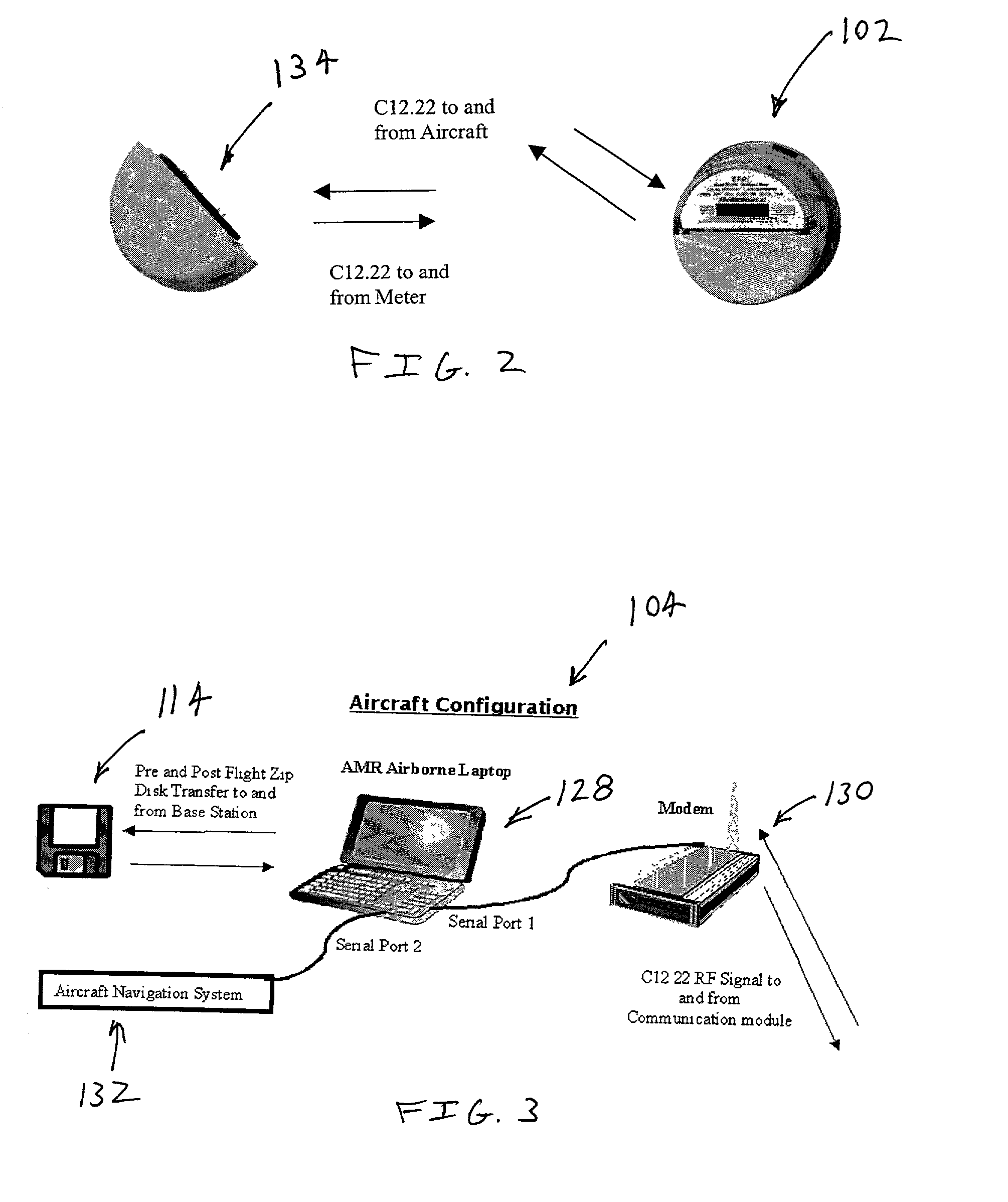
[0059] As explained above, the SE-240 meter is modified in the first exemplary embodiment by rotating it 180 degrees so that the RF module 134 resides on the upper half of meter 102 when it is connected to the SE-240 meter. This allows the antenna in RF module 134 to be optimally positioned relative to the SE-240 to communicate with airborne platform 104.

[0060] RF module 134 provides the basis to both easily command data downloads from the meter 102 to the airborne platform 104, to receive the information in the airborne platform 104 and to forward the meter data directly to the utility company or to a second party meter reading contractor.

[0061] RF module 134 includes a microprocessor that controls the module operations. The microprocessor controls the transfer of data between RF module 134 and the SE-240 meter. The microprocessor also controls communications between the RF module 134 and airborne platform 104. The processing power required for the microprocessor depends at least p...


PUM


Abstract

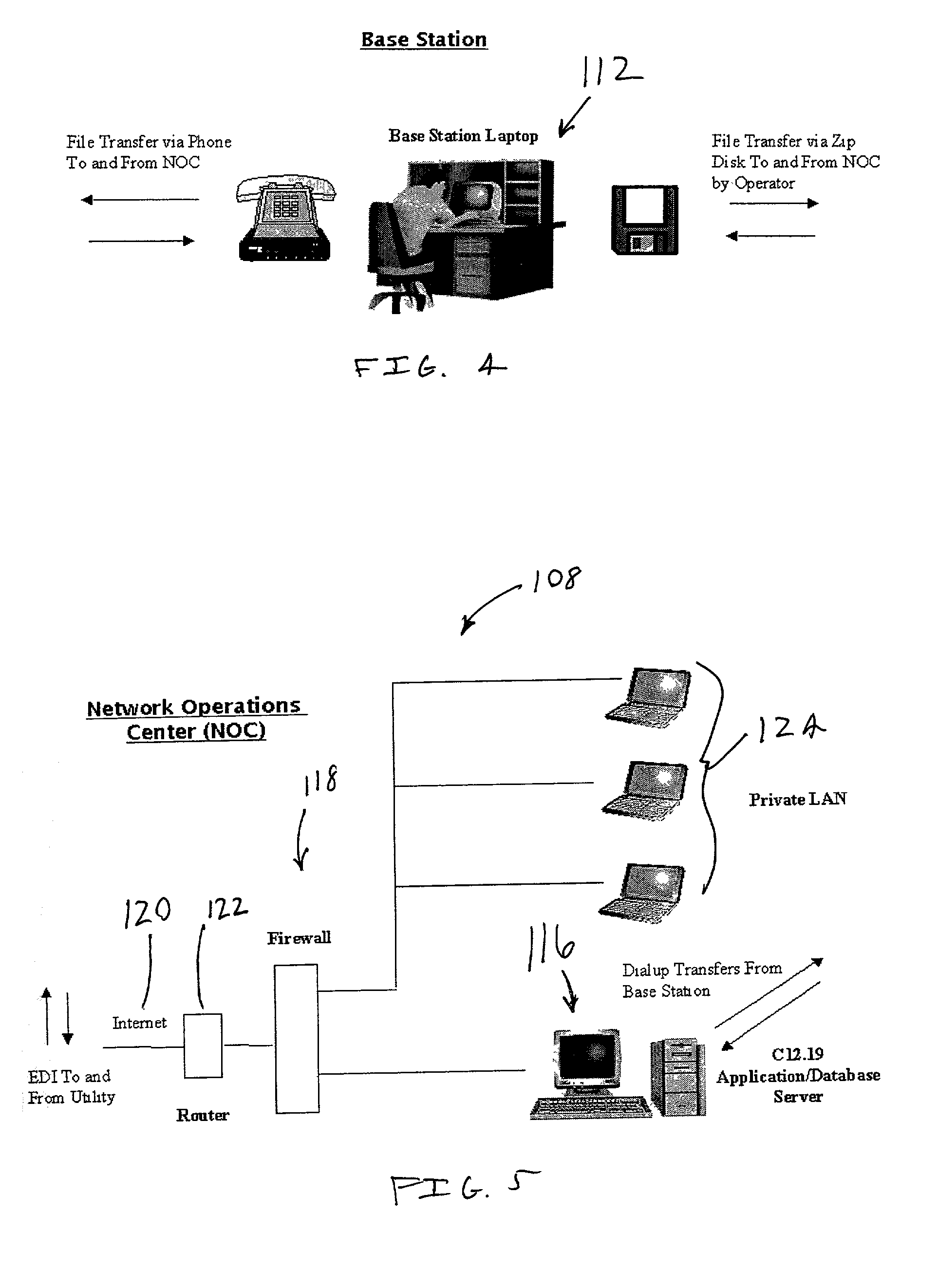
An airborne meter communication system includes an airborne platform that communicates with ground based utility meters using radio frequencies. The airborne platform retransmits information received from the meters to a network operations center for further processing.

Description

[0001] 1. Field of the Invention[0002] The present invention is directed to the art of meter reading. In particular, the invention is directed to a method and system for collecting meter readings from an airborne platform and transmitting the readings from the airborne platform to a station.[0003] 2. Description of Related Art[0004] Utility companies have traditionally employed a manpower-intensive approach to read and record the usage rates of their customer systems. Typically, the utility companies employ a legion of personnel that work selected routes to walk, drive, or ride by residential and commercial customers to read the local meter values and to record the information. This process has been performed by hand scribing the data onto blank forms, using hand-held electronic devices which connect to an interface on the meter, or by using very short-range radio frequency relayed techniques.[0005] The problems faced by these utility companies are numerous. First, the labor force t...

Claims


Application Information

Patent Timeline
IPC IPC(8): G01D4/00G08C17/02H04Q9/00
CPCG01D4/004G01D4/006G06Q50/06G08C17/02H04Q9/00Y02B90/242Y02B90/243Y04S20/322Y04S20/325Y02B90/246Y04S20/42H04Q2209/40H04Q2209/75H04Q2209/60Y02B90/20Y04S20/30
Inventor FOOTE, CHARLES A.
Owner FOOTE CHARLES A
Learn More