
Method of manufacturing a wheel rim for a two-piece vehicle wheel assembly

a two-piece vehicle and wheel assembly technology, applied in the direction of manufacturing tools, mechanical equipment, transportation and packaging, etc., can solve the problems of little incentive, difficult to obtain a high quality casting and finished wheel on a consistent basis, and look into casting and machining rims. , to achieve the effect of fewer chatter marks and finer surfa

Inactive Publication Date: 2001-11-15
SMYTH LARRY C
View PDF0 Cites 10 Cited by
  • Summary
  • Abstract
  • Description
  • Claims
  • Application Information

AI Technical Summary

Benefits of technology

[0012] It is another object of the invention to provide a method of forming a cast wheel rim which produces substantially fewer chatter marks and a finer surface after machining.
[0014] It is another object of the invention to provide a method of forming a cast wheel rim which requires less machining time.

Problems solved by technology

While this wheel was and still is largely successful, problems in manufacturing make it difficult to obtain a high quality casting and finished wheel on a consistent basis.
There was little incentive at this time to look into casting and machining rims as an alternative to sheet-formed rims in a two-piece wheel assembly.
However, because sheet rims are made from sheet, the rims are only 21 / 2 D (dimensional) shapes, i.e., they do not have the 3D shape capability that cast wheels possess in the rim area.
The two-piece all-cast wheels made using this process did not sell well, and because they were more expensive to make than either a traditional two-piece or similar looking one-piece wheel, these earlier cast and machined alloy rims were discontinued.
Although this process produces high quality rims, it is problematic in several respects.
Because the rim casting is essentially a large diameter thin walled hoop, it is very difficult to adjust the machining lathe so as to avoid excessive chatter marks (vibration induced surface irregularities) on the machined surfaces.
Other drawbacks to this process include excessive scrap, machining cycles running at twice the rate as those for one-piece wheels, excessive technician set-up time, low cutting insert life, and an extra sanding step required to smooth out the course machining and / or chatter marks in the subsequent rim polishing process.
Generally, although various remedies have been explored and minor improvements made, this process is only half as efficient as normal casting and machining for one-piece wheels.

Method used


Image

  • Method of manufacturing a wheel rim for a two-piece vehicle wheel assembly
  • Method of manufacturing a wheel rim for a two-piece vehicle wheel assembly
  • Method of manufacturing a wheel rim for a two-piece vehicle wheel assembly

Examples


Embodiment Construction

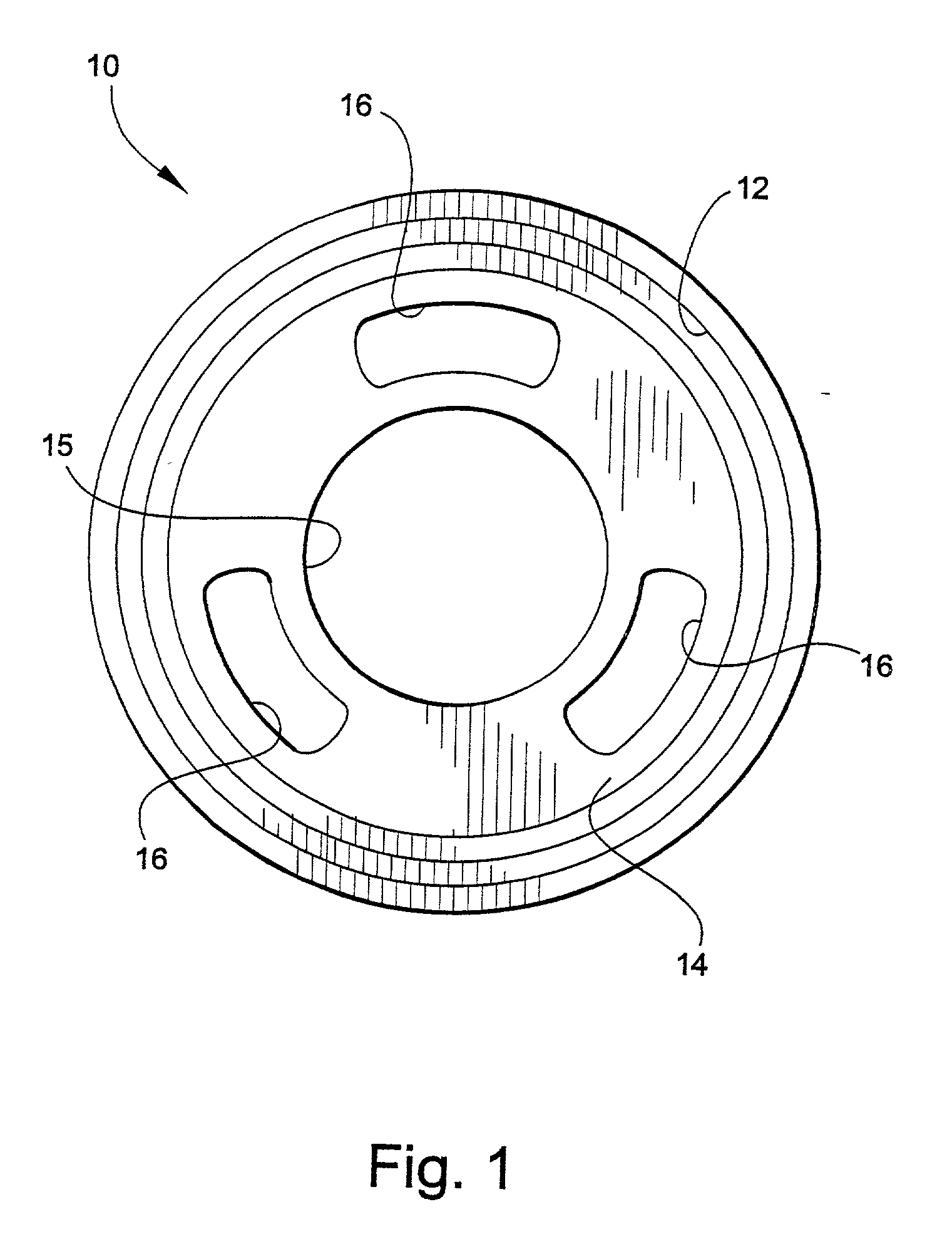
[0037] Referring now specifically to the drawings, a cast alloy wheel form is illustrated in FIG. 1 and shown generally at reference numeral 10. The wheel form 10 is processed according to a method of the present invention to form a 21 / 2 or 3-dimensional, cast alloy wheel rim adapted for use in a two-piece vehicle wheel assembly. The wheel form 10 includes an integrally-formed rim blank 12 and supporting center 14. The center 14 has a pilot bore 15 and several cast windows 16 for receiving wheel alignment and clamping members described below.

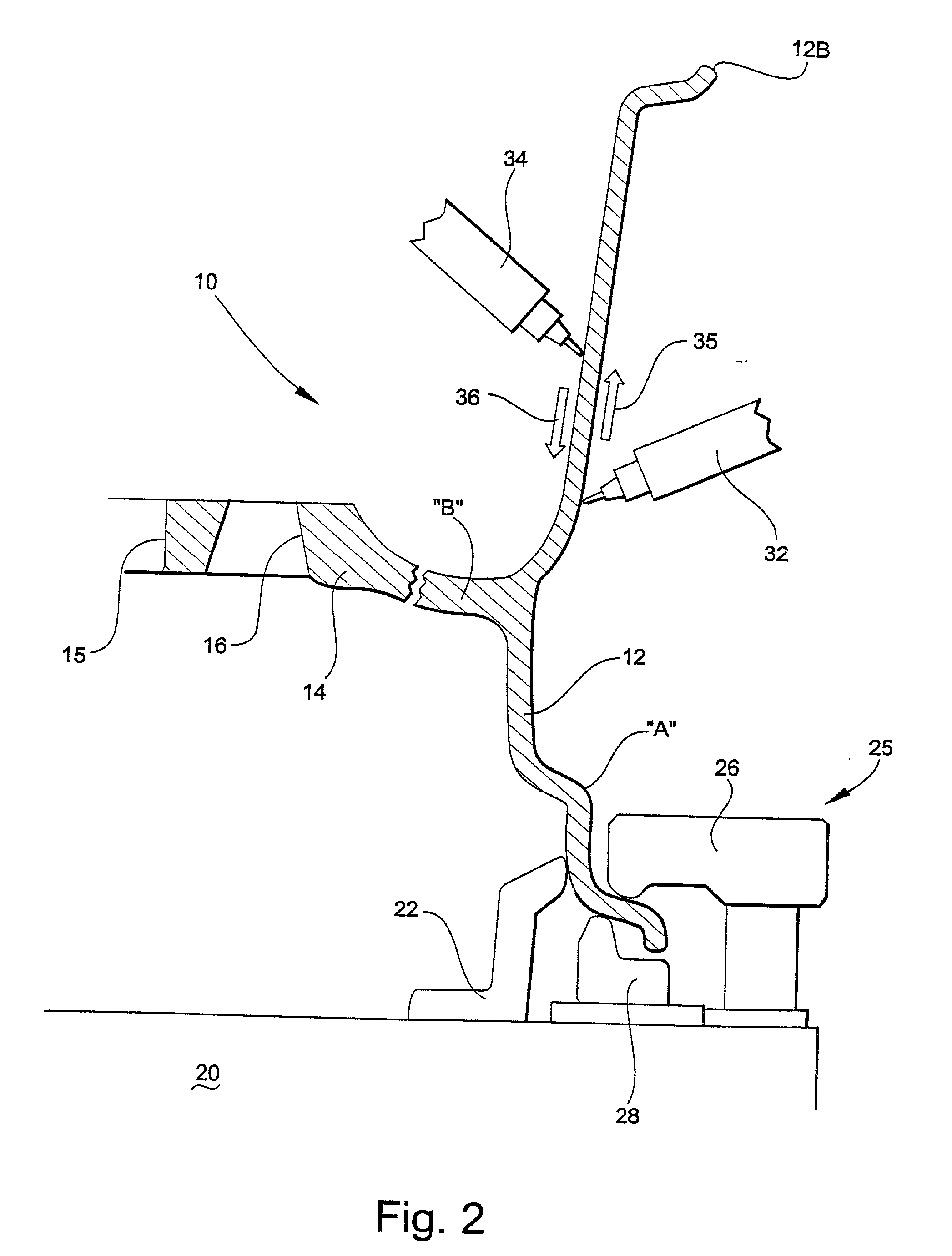
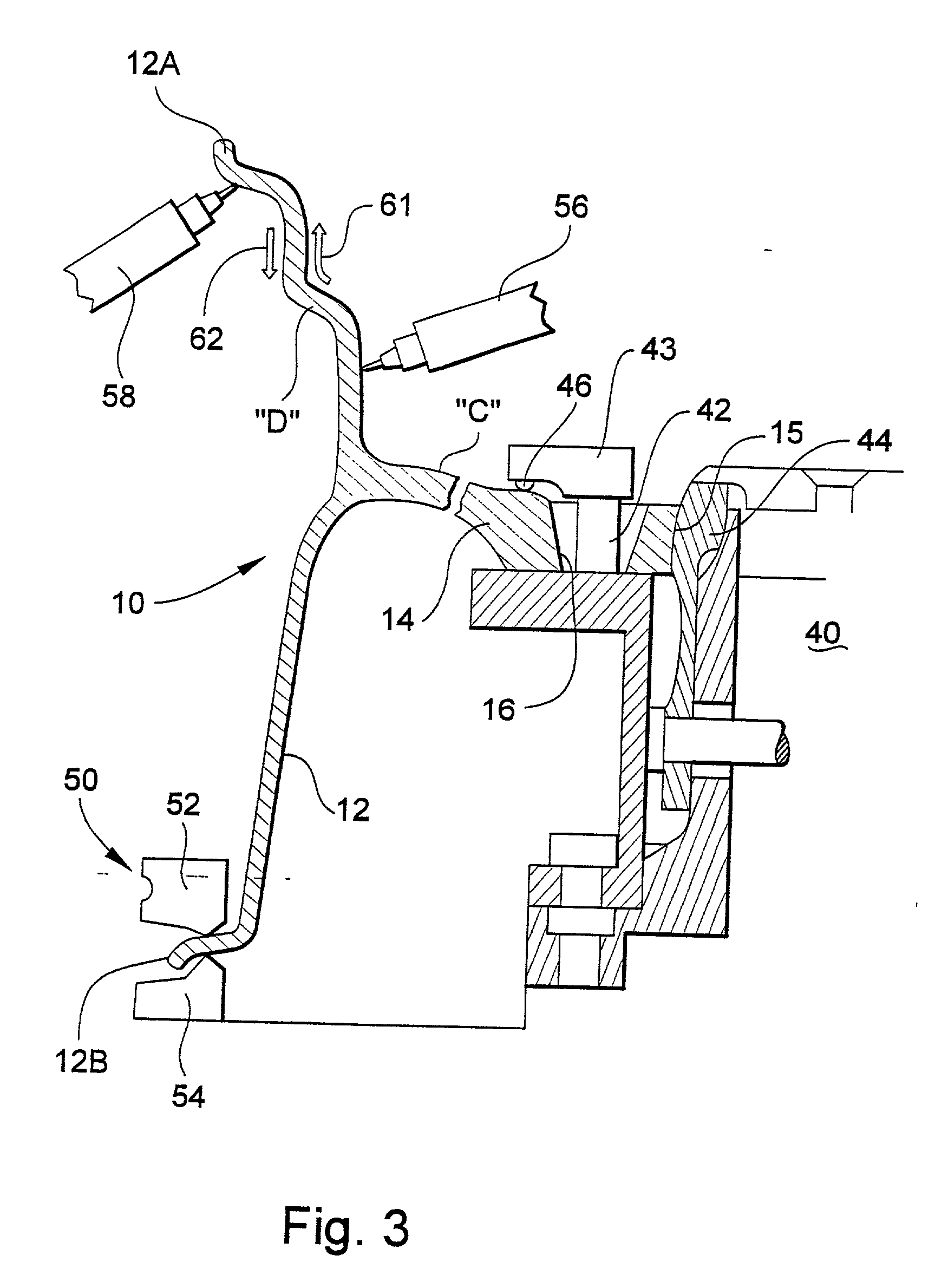
[0038] Referring to FIG. 2, after casting, the alloy wheel form 10 is mounted on a wheel chuck 20 in a vertical lathe. The wheel chuck 20 has a spring-loaded centering device 22 and clamping assembly 25 for engaging and holding an annular edge portion 12A of the rim blank 12. The clamping assembly 25 includes a vertically adjustable flange clamp 26 which bears against an outside surface of the rim edge, and a stationary rest pad 28 which bears a...


PUM

PropertyMeasurementUnit
strengthaaaaaaaaaa
toughnessaaaaaaaaaa
lengthaaaaaaaaaa

Abstract

A method for manufacturing a wheel rim for a two-piece vehicle wheel assembly. The method includes the step of providing a one-piece alloy wheel form defining an integrally-formed annular rim blank and a rigidifying flange. The rim blank includes first and second edge portions. At least one of the first and second edge portions of the rim blank is shaped. After the shaping step, the one-piece wheel form is cut to separate the shaped wheel rim from the rigidifying flange.

Description

TECHNICAL FIELD AND BACKGROUND OF INVENTION[0001] This invention relates to a method of manufacturing a wheel rim for a two-piece vehicle wheel assembly. The invention is especially applicable to the automobile parts industry.[0002] One of the largest aftermarket niches in the automobile industry is the manufacture and sale of upgraded alloy wheels. Wheels are a major styling feature which can quickly freshen the appearance of older vehicles, or customize the appearance of new vehicles still at the dealership. Traditionally, aluminum alloy wheels have been cast in one-piece with integrally-formed rim and center sections.[0003] The one-piece wheel was first introduced in the industry as an aftermarket product about 40 years ago. While this wheel was and still is largely successful, problems in manufacturing make it difficult to obtain a high quality casting and finished wheel on a consistent basis. Various manufacturing techniques have been tried in an effort to make a better product...

Claims


Application Information

Patent Timeline
Patent Type & Authority Applications(United States)
IPC IPC(8): B23P15/00B60B21/02
CPCB23P15/00B60B21/02Y10S72/701Y10T29/49526Y10T29/49799Y10T29/49989Y10T29/49524Y10T29/49499Y10T29/49813
Inventor SMYTH, LARRY C.
Owner SMYTH LARRY C
Learn More