Laser lap welding process of welding together overlapped plated steel sheets

Inactive Publication Date: 2001-12-06
FUJI JUKOGYO KK
View PDF0 Cites 45 Cited by
  • Summary
  • Abstract
  • Description
  • Claims
  • Application Information

AI Technical Summary

Problems solved by technology

However, galvanized steel sheets must be galvanized in a large coating weight because zinc coating steel sheets is relatively rapidly corroded.
Consequently, the sealed zinc vapor causes the formation of many weld defects that spoil beads, including blow holes in beads, depressions in the surfaces of beads and pits penetrating beads.
However, the vapor is unable to escape completely before melted parts of the plated steel sheets solidify when the height of the gap between the joining surfaces, i.e., the distance between the joining surfaces, is excessively small and the aforesaid weld defects are formed in welded parts.
On

Method used


Image

  • Laser lap welding process of welding together overlapped plated steel sheets
  • Laser lap welding process of welding together overlapped plated steel sheets
  • Laser lap welding process of welding together overlapped plated steel sheets

Examples


second embodiment

[0052] A laser lap welding process in a first example of the laser lap welding process in the second embodiment will be described with reference to FIGS. 6 and 7.

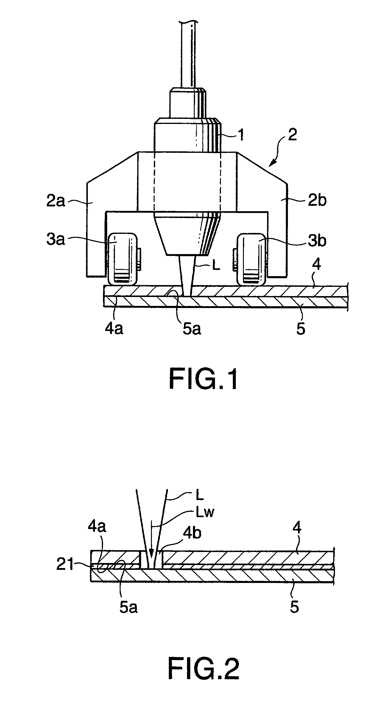
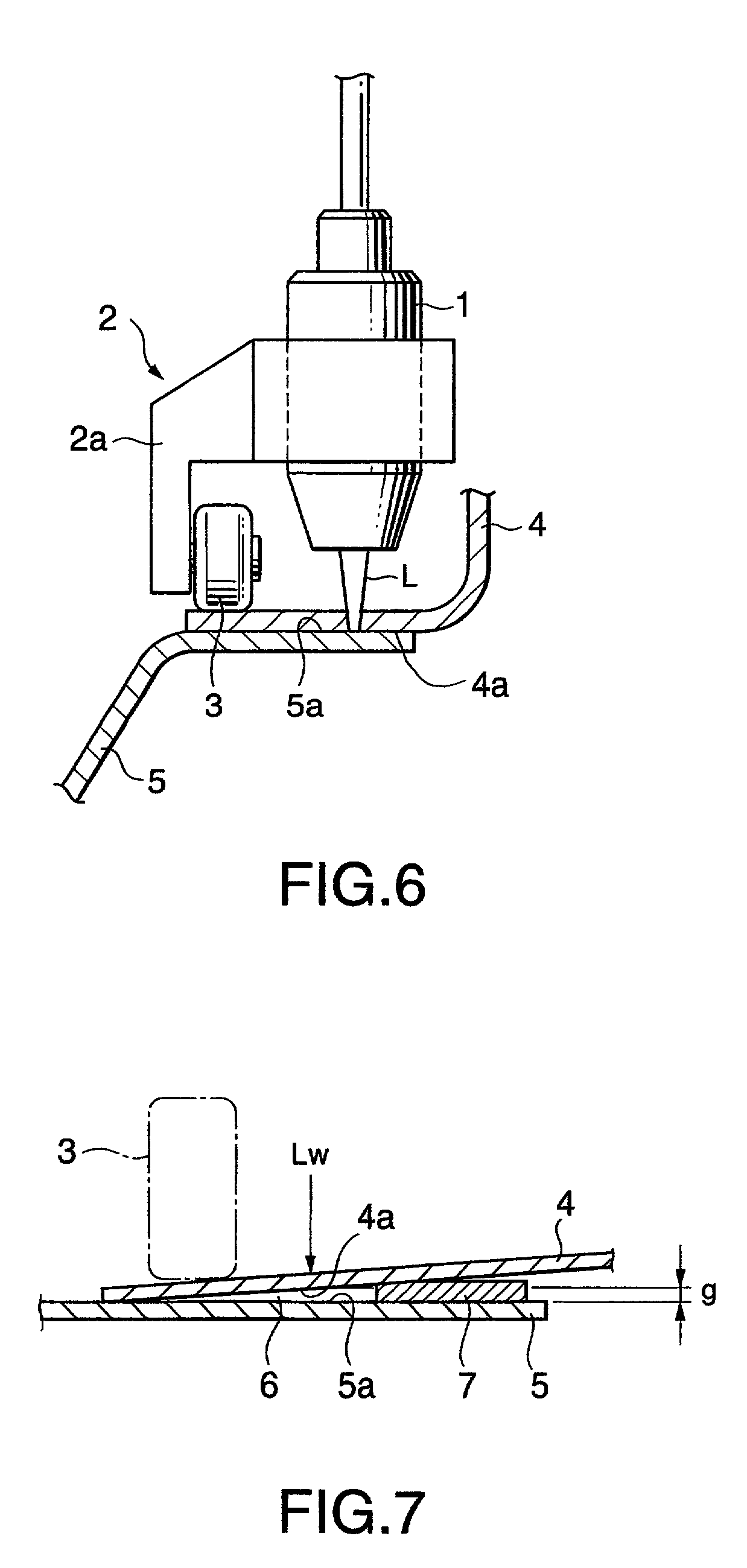
[0053] FIG. 6 is a view of assistance in explaining a laser lap welder employed in carrying out a laser lap welding process in a second embodiment according to the present invention. Referring to FIG. 6, the laser lap welder has a welding head 1 and a carriage 2 fixed to the welding head 1. Two plated steel sheets 4 and 5 are overlapped. The carriage 2 has a support leg 2a extending vertically downward from a body fixed to the welding head 1. A pressure roller 3 is supported for rotation on a lower end part of the support leg 2a. The pressure roller 3 presses a part of the upper plated steel sheet 4 near a part of the same to be irradiated with a laser beam.

[0054] The welding head 1 is held on a robot arm, not shown, or the like and is moved along a weld line Lw on the two overlapped plated steel sheets 4 and 5 by the robot...

third embodiment

[0074] A laser lap welding process in a third embodiment of the present invention will be described with reference to FIGS. 12 to 17.

first example

[0075] A laser lap welding process in a first example of the third embodiment will be described with reference to FIGS. 12 to 14.

[0076] FIG. 12 is a view of assistance in explaining a laser lap welder employed in carrying out the third embodiment of the present invention. Referring to FIG. 12, the laser lap welder has a welding head 1 and a carriage 2 fixed to the welding head 1. Two plated steel sheets 4 and 5 are overlapped. The carriage 2 has a support leg 2a extending vertically downward from a body fixed to the welding head 1. A pressure roller 3 is supported for rotation on a lower end part of the support leg 2a. The pressure roller 3 presses a part of the upper plated steel sheet 4 near a part of the same to be irradiated with a laser beam.

[0077] The welding head 1 is held on a robot arm, not shown, or the like and is moved along a weld line Lw on the two overlapped plated steel sheets 4 and 5 by the robot arm. The pressure roller 3 presses a part of the upper plated steel sh...


PUM

PropertyMeasurementUnit
Heightaaaaaaaaaa
Distanceaaaaaaaaaa

Abstract

Prior to welding together two overlapped plated steel sheets 4 and 5 by laser lap welding that irradiates parts of the plated steel sheets (4, 5) extending on a weld line (Lw), slits (4b) are formed intermittently in the upper plated steel sheet (4) with a laser beam (L). Subsequently, a welding head (1) is moved along the weld line (Lw) while the upper plated steel sheet (4) is pressed against the lower plated steel sheet (5) by pressure rollers. Parts of the upper plated steel sheet (4) extending on the weld line (Lw) and not provided with the slits (4b) are irradiated with the laser beam to laser-weld the plated steel sheets (4, 5) together. A vapor of the component of the coating layers coating the joining surfaces (4a, 5a) of the plated steel sheets (4, 5) produced from the coating layers by the heat produced by the laser beam is discharged through the slits (4b). After thus laser-welding together the plated steel sheets (4, 5), the slits (4b) of the upper plated steel sheet (4) are stopped with a molten metal produced by melting a filler with the laser beam.

Description

[0001] 1. Field of the Invention[0002] The present invention relates to a laser lap welding process of welding together plated steel sheets for forming automotive bodies or the like.[0003] 2. Description of the Related Art[0004] Galvanized steel sheets, i.e., surface-treated steel sheets, have been used in the automobile industry. However, galvanized steel sheets must be galvanized in a large coating weight because zinc coating steel sheets is relatively rapidly corroded.[0005] Hot-dip galvanealed steel sheets are prevalently used. A hot-dip galvanealed steel sheet is manufactured by plating a steel sheet with molten zinc by hot dipping to form a zinc-coated steel sheet, subjecting the zinc-coated steel sheet to an alloying process to suppress the activity of the zinc coating by forming an alloy layer on the surface of the steel sheet through the mutual diffusion of Fe and Zn. The coating weight of the zinc coating of such a hot-dip galvanealed steel sheet, as compared with that of ...

Claims


Application Information

Patent Timeline
IPC IPC(8): B23K26/02B23K33/00
CPCB23K26/023B23K26/246B23K26/3206B23K26/3293B23K33/004B23K2203/04B23K26/037B23K26/32B23K26/244B23K2101/34B23K2103/04B23K2103/08B23K2103/50
Inventor DEGAWA, HIDETAKAKOJIMA, SHOJINAGASE, TOMOTAKASAITO, HIROKIHOSHINO, KAZUYUKIUEDA, SATOSHITOMITA, KOJIKAWAI, KOSUKESHIMAZAKI, HIROSHI
Owner FUJI JUKOGYO KK
Why Eureka
Try Eureka