Hence, the drive of the developing roller becomes unavoidably intermittent owing to the backlash in the mesh of the gears, causing feed irregularities to occur on the developing roller.
As a result, density unevenness (banding) occurs in the feed direction.
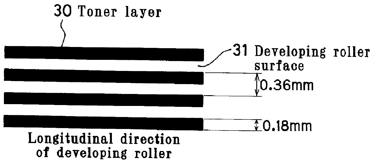
Further, when the thickness of the toner layer on the surface of the developing roller is regulated with the regulating blade, toner is likely to clog in the nip between the developing roller and the regulating blade.
Further, blur may occur in a
halftone image owing to disconnection, thickening or scattering of thin lines of the image.
When printing is performed continuously, toner may adhere to the developing roller to give rise to a problem known as filming.
This causes the toner transferability and chargeability to change, resulting in
image quality degradation.
As a result, small toner particles are repeatedly stirred and pressed, causing filming on the developing roller and the regulating blade (i.e. the problem in terms of durability).
However, this development method involves the problem that it is costly because a
magnet is installed on the developing sleeve, and the method cannot cope with the demand for
color image formation.
There are also problems inherent to this method.
Consequently, there may be undesired tailing produced by toner left uncollected by magnetic force (i.e. a phenomenon in which a trail of toner is undesirably left behind the image).
With this method, the amount of toner conveyed is large, but on the other hand, charging of toner is likely to become insufficient, causing
fogging.
Problems to be solved for the non-magnetic one-component development, exclusive of the magnetic
brush development, include
gradation degradation due to
edge enhancement and an increase in density at the trailing end of the image.
There is an image forming apparatus in which an image is formed by developing an electrostatic latent image formed on a latent image carrier (photosensitive member) by using a contact developing device arranged to apply an AC-superimposed bias voltage to a developer carrier (developing roller) This type of image forming apparatus involves the problem that the resulting image is unfaithful to the latent image and inferior in
gradation reproduction and
halftone reproduction and hence suffers from poor image quality.
However, the amplitude (V.sub.pp) of the AC-superimposed bias voltage cannot sufficiently be increased because of such restrictions as the injection of an
electric charge into the latent image carrier and background fogging.
Accordingly, the conventional image forming apparatus of this type is not at a practical level.
However, this method involves the problem that
noise may be generated depending on the screen structure or other factors.
For example, if a
halftone dot screen is used in a case where a line-shaped conveying surface is formed on the developer carrier, banding (lateral unevenness) occurs unfavorably.
Further, if the frequency of the screen in the feed direction synchronizes to the frequency of a line-shaped conveying surface generated by application of an AC-superimposed bias voltage, density unevenness occurs on the latent image carrier.
If the frequency of the screen in the feed direction synchronizes to the frequency of the nip variations due to the
superimposition of the
alternating current, density unevenness occurs on the latent image carrier.

