Process for the production of metal melts

a technology of metal melt and process, which is applied in the direction of manufacturing converters, furnaces, lighting and heating apparatuses, etc., can solve the problems of inability to achieve conventional electric arc furnaces, and inability to achieve quasi-stationary continuous process

Inactive Publication Date: 2002-01-17
VOEST ALPINE AG
View PDF0 Cites 18 Cited by
  • Summary
  • Abstract
  • Description
  • Claims
  • Application Information

AI Technical Summary

Benefits of technology

[0030] The plant in accordance with the invention in addition to solving the problem defined above offers the advantage that in case of continuous tapping the refractory lining of the plant parts is subjected to no and in case of discontinuous tapping only to slight strains resulting from changes in temperature.
[0038] According to a preferred embodiment, the electric arc furnace vessel is provided with at least one preheating shaft supplying solid iron carriers which is arranged above the electric arc furnace vessel and preferably at the side thereof or annularly above the furnace vessel, thus enabling preheated scrap and / or sponge iron or other iron carriers to be charged in a simple manner and while utilizing the heat content of the offgases arising in the electric arc furnace vessel. The preheating shaft may be arranged centrally or at a de-centralized position and preferably is not provided with gas-permeable shut-off devices (fingers), i.e. the preheating shaft discharges into the electric arc furnace vessel directly and without any obstacles, with the solid iron carriers forming a column having its base on the bottom of the electric arc furnace vessel.
[0049] For easier handling, the lid of the electric arc furnace vessel and the lid of the oxygen-blowing converter vessel form a unit or are configured as a unit.
[0051] To avoid major interruptions when individual plant parts are in need of repair, an advantageous embodiment is characterized in that the oxygen-blowing converter vessel is constructed as a structural unit separable from the electric arc furnace vessel and exchangeable.
[0062] For better utilizing the energy, the offgases employed for preheating are afterburned step-by-step during the preheating process.

Problems solved by technology

However, with the known processes for the production of electric steel by means of electric arc furnaces used as melting aggregates, the potential advantages of the above-mentioned process developments have been utilized to a limited extent only.
Moreover, it has not been feasible so far--despite an increasing demand--to process to liquid steel high portions of liquid pig iron and / or other carbon-rich iron carriers (sponge iron, iron carbide etc.) as well as problem scrap (used cars) of about 30 to 70% charged into electric arc furnaces, at a high productivity and energy utilization and, with car scrap, also without inadmissible loads on the environment.
The above-mentioned limitations with conventional electric arc furnaces are due exclusively to the configuration of the furnaces, which does not enable a quasi-stationary continuous process course.
The present process course in an electric arc furnace is discontinuous and hence limited in its performance.
The refining zone is constructed as a channel-type reactor, resulting in a high specific surface area with high heat losses.
Refining is carried out with a C-concentration gradient along the refining zone of the channel-type reactor without a concentration balancing tank, and therefore the C content is difficult to adjust or control.
Consequently, that known process is applicable to a limited extent only, in the first place serving to produce crude steel from prereduced ore.
On the one hand, this causes an increased wear of the refractory lining and hence elevated material and time costs for doing repairs.
In addition, a large portion of the input energy is imparted by radiation to the furnace walls and the furnace lid and thereby gets lost.
Moreover, possible bridging within the scrap column--above the melt caverns melted into it by the electrodes--may cause precipitation of the scrap column (or parts thereof), which might lead to a break of the electrodes and hence interrupt the process.
One disadvantage associated with this method are the difficulties in adjusting the crude steel temperature immediately before starting and while performing the tapping operation, since there is a very large contact area of the scrap, which is arranged in the shape of a ring, with the liquid bath.
There may also arise difficulties in respect of the balancing out of concentrations or in respect of the chemical homogeneity of the melt which is refined and tapped discontinuously with this process.
However, no optimum gas utilization results in this process, since the scrap is not streamed through by the offgas but the latter only passes across the same.
The structure as such is thus expensive, as with all pivotable furnaces.
There results mechanical wear of the refractory furnace lining.
As a result, the melting and mixing operations cannot be carried out in an optimum manner, and in using burners in the electric furnace to support melting of the scrap only a low efficiency would be achieved.

Method used


Image

  • Process for the production of metal melts
  • Process for the production of metal melts
  • Process for the production of metal melts

Examples


exemplary embodiments 1 and 2

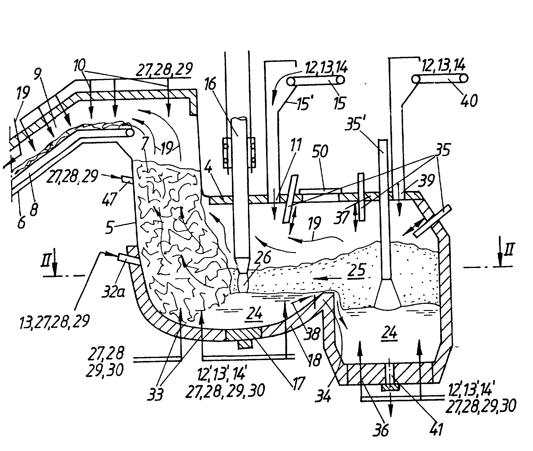
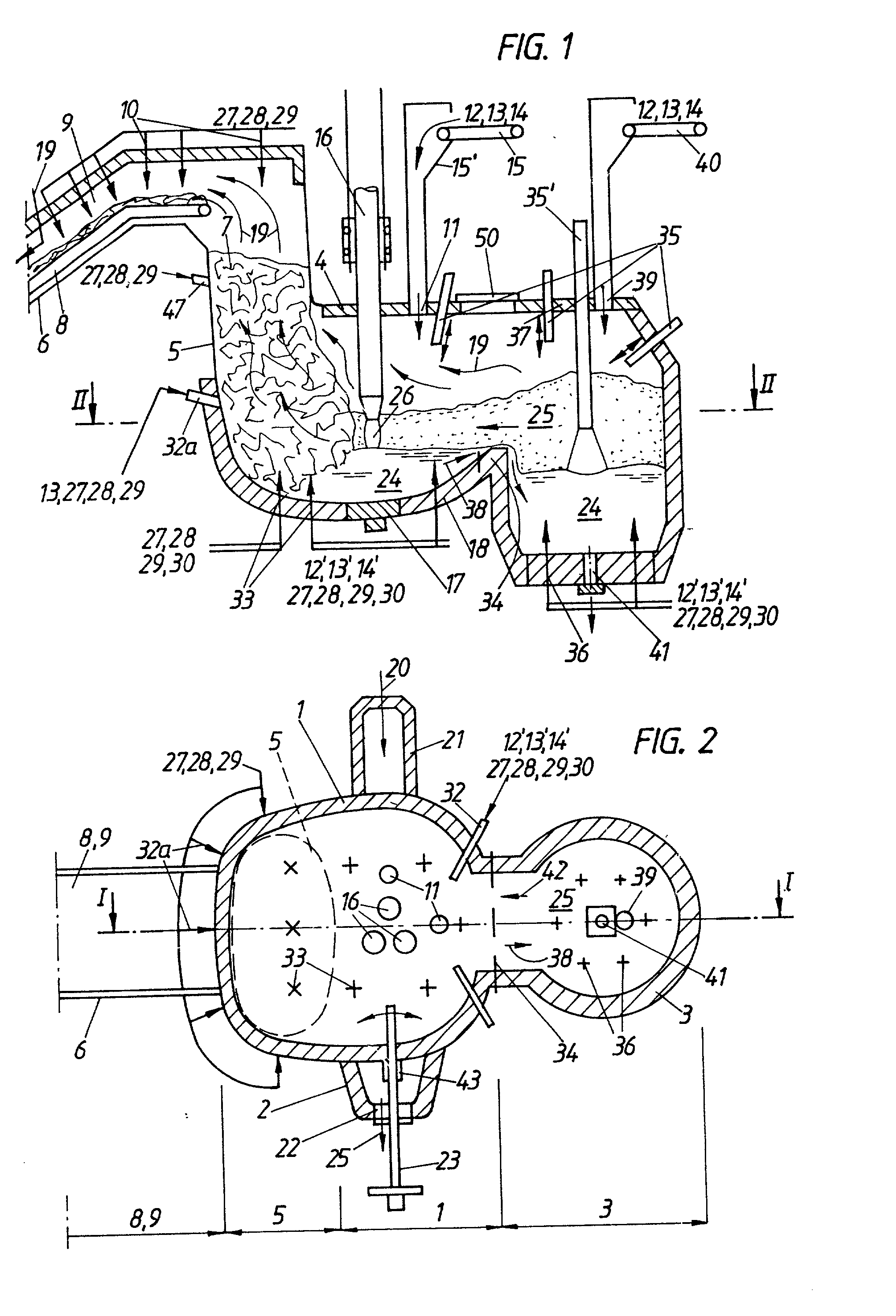
[0245] Plant according to FIG. 1 comprising

[0246] a heating part 9 (conveyor belt 8 with preheating function)

[0247] a scrap preheating shaft 5 of oval cross-section

[0248] a furnace vessel 1 configured as an AC-EAF as a melting and prefining vessel

[0249] a converter vessel 3 of the type LD-S* *coverter with inert-gas bottom flushing N.sub.2 / Ar

[0250] a decanting part 2 associated with the furnace vessel 1

Exemplary Embodiment 3

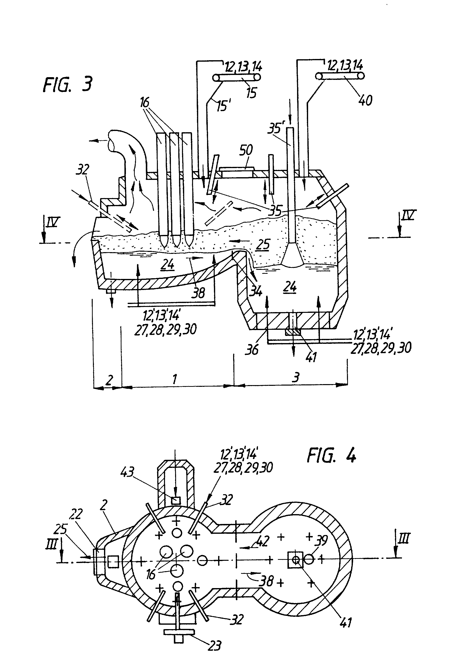
[0251] Plant according to FIG. 3, comprising

[0252] an AC electric arc furnace as the furnace vessel 1, as the melting and prefining vessel

[0253] a converter vessel 3 of the type LD-S* *coverter with inert-gas bottom flushing N.sub.2 / Ar

[0254] a decanting part 2

4TABLE II Chemical composition and temperature of the Fe-containing charging substances steel scrap 0.30% C 2.5% ashes 0.50% Mn 0.2% moisture 0.20% Si 0.030% S 25.degree. C. 0.020% P sponge iron pellets 91.9% FE.sub.tot (MIDREX-DRI) 92.9% degree of metallization 1.8% C 4.6% gangue about 0.5 gangue basicity 2...

exemplary embodiment 1

[0303] The charge mix consists of 100% steel scrap (mixed scrap) having the composition shown in Table II. The process is carried out using the plant variant according to FIG. 1 with the scrap preheating shaft 5 having an internal effective cross-section of 11.5 m.sup.2 and with two scrap conveying belts 8 (each with a belt width of 2.0 m and a belt length of 40 m), which are arranged in parallel side by side and prior to unloading the scrap 7 into the preheating shaft 5 pass through a common heating part 9 which is 10 m in length, with the heating part 9 opening directly into the upper hood region of the preheating shaft 5.

[0304] A small partial amount (1.50%) of the scrap with a piece size .ltoreq.100 mm is fed into the converter vessel 3 continuously as a cooling agent 12 at a temperature of 25.degree. C. The rest of the scrap, which has a max. length of the scrap pieces of 1.5 m (i.e. the principal partial amount 7 of 88.50%), is charged onto the two scrap conveying belts 8 by m...

exemplary embodiment 2

[0356] The charge mix consists of

[0357] 40% steel scrap

[0358] 30% sponge iron (pellets) and

[0359] 30% liquid pig iron

[0360] having the properties presented in Table II.

[0361] In the instant case, there is principally no essential difference compared with the Exemplary embodiment 1 presented above as far as the plant configuration and the fundamental process course to be employed are concerned. Differences with respect to plant configuration and process control result from the different quantitative ratios and properties of the components in the charge mix. The process is likewise carried out using the plant variant according to FIG. 1, yet

[0362] employing the scrap preheating shaft 5 having the small effective cross-section of about 5 m.sup.2, wherein the difference with respect to the scrap preheating shaft 5 having the large effective cross-section of about 11.5 m.sup.2 is made up for by providing an additional lid piece in the lid 4 of the furnace vessel 1, which piece matches th...


PUM

PropertyMeasurementUnit
angleaaaaaaaaaa
temperatureaaaaaaaaaa
angle of inclinationaaaaaaaaaa

Abstract

To be able to produce metal melts using any metal carriers incurring in metallurgical practice as the charging materials, namely in the most diverse quantitative compositions, a plant for producing metal melts is provided with the following characteristic features: an electric arc furnace vessel (1) provided with one charging opening (11, 21) for a metal melt and / or scrap and / or direct educed metal, in particular direct reduced iron, and / or ore and at least one electrode (16) and one slag tapping means (22), an oxygen-blowing converter vessel (3) provided with one melt tapping means (41), wherein the oxygen-blowing converter vessel (3) and the electric arc furnace vessel (1) form a unit which is connected via an overflow weir (34) and which is rigidly mounted on the foundation and, wherein the bath surface related specifically to the bath volume is smaller in the oxygen-blowing converter vessel (3) than in the electric arc furnace vessel (1) and the oxygen-blowing converter vessel (3) shares a common reaction space with the electric arc furnace vessel (1), which space is arranged above the bath level of these vessels.

Description

[0001] This is a division of application Ser. No. 09 / 258,755 filed Feb. 26, 1999, which is a continuation application of International Application PCT / AT98 / 00160 having an international filing date of Jun. 26, 1998.[0002] 1. Field of the Invention[0003] The invention relates to a plant for the production of metal melts, in particular iron melts, such as steel melts, crude steel melts or pig iron melts, and a process for the production of these melts.[0004] 2. Description of the Related Art[0005] The present standard aggregate used for the production of electric steel is an a.c. or d.c. electric arc furnace. The iron carriers charged, which are comprised of[0006] 60 to 100% steel scrap, directly reduced iron-sponge iron in various quantitative ratios and sometimes also iron carbide (at present, up to about 10 to 20% of the total charge), and[0007] 0 to 40% liquid and / or solid pig iron[0008] are melted by aid of one or several electric arcs using oxygen lance(s)--if desired, burner(s)...

Claims


Application Information

Patent Timeline
Patent Type & Authority Applications(United States)
IPC IPC(8): F27B3/08C21C5/36C21C5/52C21C5/56F27B3/04F27B3/18F27B3/22F27B19/04
CPCC21C5/5252C21C5/562C21C5/567C21C2005/366C21C2300/02F27B3/045F27B3/186F27B3/225F27B19/04Y02P10/20C21C5/56
Inventor DIMITROV, STEFANRAMASEDER, NORBERTPIRKLBAUER, WILFRIEDZHAI, YOYOUSTEINS, JOHANNESFRITZ, ERNSTMULLER, JOHANNES
Owner VOEST ALPINE AG
Why Eureka
Try Eureka