Image signal transmission apparatus

a technology of image signal and transmission apparatus, which is applied in the direction of color television with bandwidth reduction, television system, instruments, etc., can solve the problems of transmission cable reaching its own physical limit, image deterioration, and difficulty in providing such transmissions by this method

Inactive Publication Date: 2002-01-17
SANYO ELECTRIC CO LTD
View PDF1 Cites 31 Cited by
  • Summary
  • Abstract
  • Description
  • Claims
  • Application Information

AI Technical Summary

Problems solved by technology

[1] In a case of transmitting image signals produced in a personal computer to a display device via an analog transmission cable, if the analog transmission cable is long, it is apt to cause image deterioration.
It becomes, however, difficult for this method to provide such transmissions if the resolution of image data is further raised up to an ultrahigh resolution of 1600.times.1200 pixels (UXGA), 2048.times.1536 pixels (QXGA) or the like which causes the transmission cable to reach its own physical limit.
It is difficult for the "PanelLink" method to effect the transmission of an ultrahigh resolution, such as UXGA, QXGA or the like, and / or effect a long-distance transmission.
[3] In a case of transmitting image signals produced in a personal computer to a liquid crystal projector via an analog transmission cable, if the analog transmission cable is long, it is apt to cause image deterioration.
Meanwhile, in the image signal transmission apparatus of the "LVDS" or "PanelLink" method, if the amplitude of signals to be transmitted is enlarged, it increases the possible distance of transmission by the cable but also increases unwanted radiation signals.
In contrast to this, if the amplitude of signals to be transmitted is reduced, it reduces the unwanted radiation signals but also reduces the possible transmission distance.
The "LVDS" method, however, has no function to adjust the signal amplitude.
However, since the external resistor 165 is disposed at the stage of design, it is difficult for the user to adjust the signal amplitude according to the cable length.

Method used


Image

  • Image signal transmission apparatus
  • Image signal transmission apparatus
  • Image signal transmission apparatus

Examples


first embodiment

[0073] the present invention will be described below with reference to FIGS. 5 to 7.

[0074] FIG. 5 shows the structure of a digital image signal transmission apparatus. This image signal transmission apparatus comprises a transmission unit 10 set in a personal computer, a liquid crystal projector 20 and a cable 30 connecting them.

[0075] The transmission unit 10 includes a VGA controller (graphic chip) 11, a switch circuit 12, a CPU 13, a one-phase to two-phase converter circuit 14, a first PanelLink transmitter 15 and a second PanelLink transmitter 16.

[0076] The liquid crystal projector 20 includes a first PanelLink receiver 21, a second PanelLink receiver 22 and a liquid crystal panel 23 of digital drive type. The first PanelLink receiver 21 incorporates a one-phase to two-phase converter circuit 21a.

[0077] The cable 30 comprises six pairs of signal lines for transmitting image data and one pair of signal lines for transmitting a clock signal.

[0078] The CPU 13 detects which the imag...

second embodiment

[0092] [2] Description of Second Embodiment

[0093] A second embodiment will be described below with reference to FIGS. 8 to 10.

[0094] FIG. 8 shows the structure of a digital image signal transmission apparatus.

[0095] This image signal transmission apparatus comprises a transmission unit 10 set in a personal computer (PC) 1, a receiving-side unit 105 set in a liquid crystal projector 20, and a cable 30 connecting the transmission unit 10 and the receiving-side unit 105.

[0096] The transmission unit 10 includes a graphics controller (graphic board) 101, a switch circuit 102, a one-phase to two-phase converter circuit 103 and a transmitting-side unit 104. The graphics controller 101 is connected to a main CPU 2 in the PC 1 via a bus 3 also therein. The main CPU 2 is connected to a line receiver 146. The transmitting-side unit 104 includes first and second PanelLink transmitters 111 and 112, respectively.

[0097] The receiving-side unit 105 in the liquid crystal projector 20 is connected to...

third embodiment

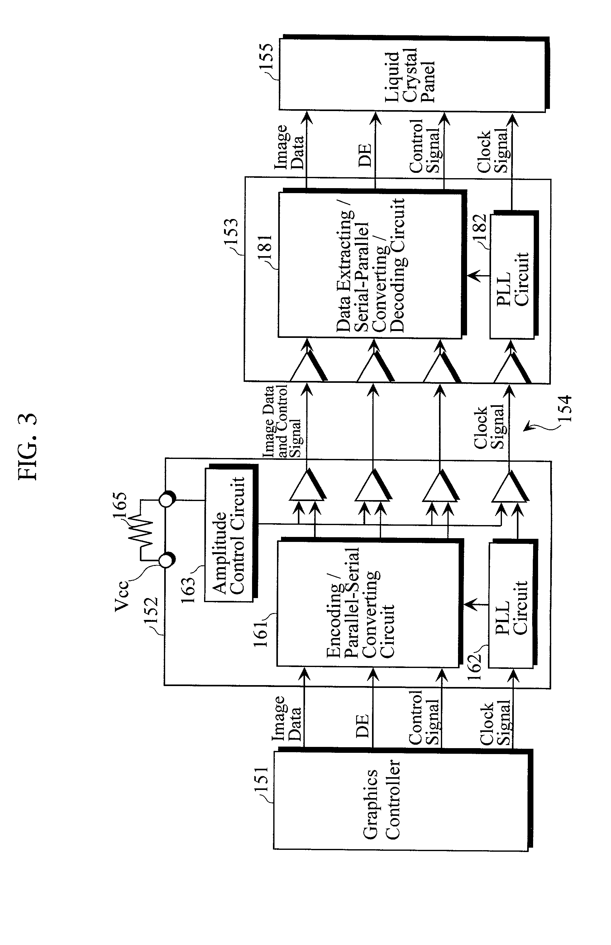
[0127] [3] Description of Third Embodiment

[0128] A third embodiment will be described blow with reference to FIGS. 11 to 14.

[0129] FIG. 11 shows the structure of an image signal transmission apparatus. In FIG. 11, elements corresponding to the same elements in FIGS. 3 and 4 are identified by the same reference designations.

[0130] This image signal transmission apparatus comprises a transmission unit 10 set in a personal computer PC 1, a receiving-side unit 153 set in a liquid crystal projector 20, and a cable 154 connecting the transmission unit 10 and the receiving-side unit 153.

[0131] The transmission unit 10 comprises a graphics controller (graphics board) 151 and a transmitting-side unit 152 connected thereto. The graphics controller 151 is connected to a main CPU 2 in the PC 1 via a bus 3 also therein. The transmitting-side unit 152 in the transmission unit 10 is connected to the receiving-side unit 153 via the cable 154. The main CPU 2 is connected to a line receiver 196.

[0132...


PUM


Abstract

An image-transmitting-side device comprises: a one-phase to two-phase converter circuit for separating parallel image data, which are to be transmitted, into even and odd data; a first parallel-serial converting circuit; a second parallel-serial converting circuit; means for allowing a user to select, as the resolution mode for the image data to be transmitted, one of a first resolution mode and a second resolution mode that is higher in resolution than the first resolution mode; and switch means for applying the parallel image data, which are to be transmitted, to the first parallel-serial converting circuit when the first resolution mode is selected, and for applying the parallel image data, which are to be transmitted, to the one-phase to two-phase converter circuit when the second resolution mode is selected.

Description

[0001] 1. Field of the Invention[0002] This invention relates to an image signal transmission apparatus for transmitting image signals produced in a personal computer to a display device, such as a liquid crystal projector, plasma display panel (PDP) or the like, which is relatively remote from the personal computer.[0003] 2. Description of the Prior Art[0004] [1] In a case of transmitting image signals produced in a personal computer to a display device via an analog transmission cable, if the analog transmission cable is long, it is apt to cause image deterioration. Such image deterioration will be noticeable especially on the display device having a high resolution of 1024.times.768 pixels (XGA), 1280.times.1024 pixels (SXGA) or the like.[0005] Some image signal transmission apparatus have already been developed that cause no image deterioration even when the transmission cables are long. An example of those apparatus is "PanelLink" by Silicon Image, Inc. in the United States, wh...

Claims


Application Information

Patent Timeline
Patent Type & Authority Applications(United States)
IPC IPC(8): G09G3/20G09G5/00
CPCG09G5/006G09G2340/0407G09G2370/045Y10S715/969
Inventor NAGAI, TAKAAKIKASAMATSU, HIDEKI
Owner SANYO ELECTRIC CO LTD
Why Eureka
Try Eureka