
Substrate fixture for high-yield production of thin film based dense wavelength division multiplexers

a technology of dense wavelength division multiplexers and substrate fixtures, which is applied in the direction of multiplex communication, optical multiplex, instruments, etc., can solve the problems of insufficient thickness control of multi-layer coatings designed for dwdm, filtering that does not meet required specifications, and insufficient performan

Inactive Publication Date: 2002-01-24
ATOMIC TELECOM
View PDF17 Cites 14 Cited by
  • Summary
  • Abstract
  • Description
  • Claims
  • Application Information

AI Technical Summary

Problems solved by technology

This level of thickness control is insufficient for multilayered coatings designed for DWDM.
Thickness non-uniformity of 0.1 percent will lead to filters that do not meet required specifications.
Customers for the filters have relaxed requirements and settled for inadequate performance to continue with installation of DWDM systems.
Currently, thin film filters for DWDM muxes and demuxes are produced with accepted yields of less than 5 percent, due to the complexity and uniformity requirements of the coatings designs.
Coating equipment used for complex optical coatings is not optimally tooled to provide necessary uniformity for this application.
Optical thickness monitors employed in most optical coating systems are not capable of resolving variations in thickness on the sub-angstrom level.
Quartz crystal thickness monitors are more sensitive to changes in thickness, but are typically used inefficiently or improperly.
This results in decreased accuracy of thickness determination vs. deposition time.

Method used


Image

  • Substrate fixture for high-yield production of thin film based dense wavelength division multiplexers
  • Substrate fixture for high-yield production of thin film based dense wavelength division multiplexers
  • Substrate fixture for high-yield production of thin film based dense wavelength division multiplexers

Examples


Embodiment Construction

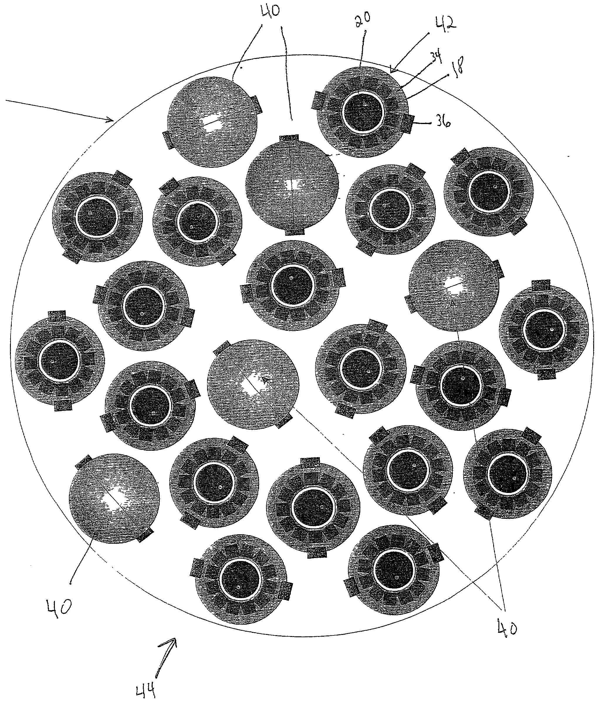
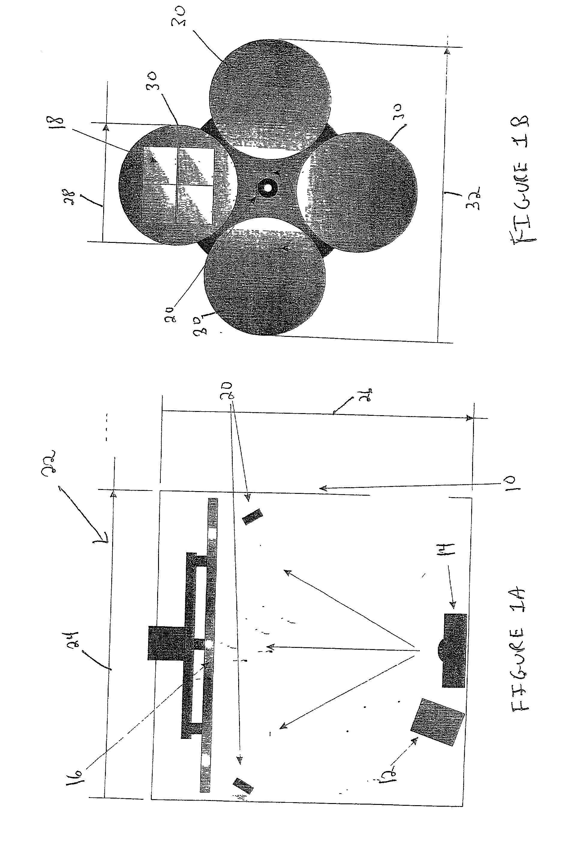
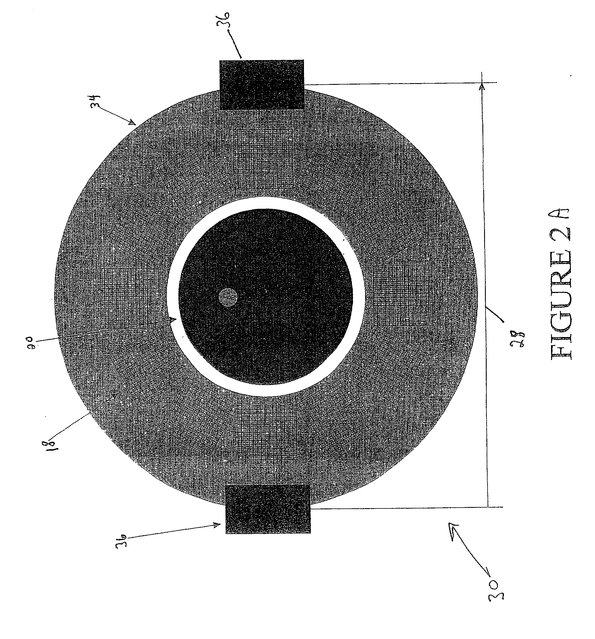
[0036] Referring now to the drawings, which are for purposes of illustrating at least one embodiment of the invention only, and not for purposes of limiting the invention, FIGS. 2A and 2B are a representation of a high yield fixture 30, call the Vomado.TM., which has been designed to produce demultiplexer filters for DWDM systems with greater than 25 percent accepted yield. The design is comprised of a disk 34 (which in this embodiment is approximately 8.5 inches in diameter) with a concentric multi-crystal QCM 20 and a dedicated shutter arrangement. In this embodiment, the disk 34 rotates at greater than 1000 rpm (the disk 34 may rotate as slowly as 500 rpm) during operation to ensure uniform deposition of material at typical coating deposition rates of 0.2-0.5 nm / s. Under these conditions, the disk 34 would perform equal to or greater than 20 revolutions for each atomic layer (monolayer) of deposited material. This ensures that angular variation of thickness is less than or equal ...


PUM

PropertyMeasurementUnit
thicknessaaaaaaaaaa
diameteraaaaaaaaaa
thicknessaaaaaaaaaa

Abstract

A substrate fixture has been designed, which significantly improves production yield of thin film based demultiplexer filters for use in Dense Wavelength Division Multiplexer (DWDM) systems. The fixture is comprised of a small area disk capable of rotational speeds greater than 1000 rpm with a dedicated concentric thin film quartz crystal thickness monitor and "clam shell" type shutter. The fixture is intended to be used in a vacuum deposition system, designed to perform optical coatings. The high-speed rotation and location of the fixture with respect to the deposition source guarantees coating thickness uniformity on substrates attached to the disk. The concentric quartz crystal thickness monitor (QCM) calibrated to the geometry or the deposition environment guarantees accurate thickness determination over the area of the disk to within 0.01 percent. The deposition system, designed to produce multilayer filters, for use as demultiplexers in DWDM systems, would utilize a dense array of fixtures of the type described herein for maximum production yield.

Description

[0001] This application claims priority to U.S. Provisional Patent Application Serial No. 60 / 217,115, entitled SUBSTRATE FIXTURE FOR HIGH-YIELD PRODUCTION OF THIN FILM BASED DENSE WAVELENGTH DIVISION MULTIPLEXERS, filed on Jul. 10, 2000 and U.S. Provisional Patent Application Serial No. 60 / 217, 060, entitled HIGH THROUGHPUT HIGH-YIELD VACUUM DEPOSITION SYSTEM FOR THIN FILM BASED DENSE WAVELENGTH DIVISION MULTIPLEXERS, filed on Jul. 10, 2000.[0002] A. Field Of The Invention[0003] The present invention relates to a high speed rotational fixture assembly that has been designed to enable high yield production of thin film based demulitiplexers for DWDM (Dense Wavelength Division Multiplexer) systems. The fixture utilizes a dedicated thin film thickness monitor and shutter to allow individual thickness control of coatings on substrates positioned at various locations in a vacuum deposition system. The individual control compensates for variations in deposition rate, which are inherent in...

Claims


Application Information

Patent Timeline
Patent Type & Authority Applications(United States)
IPC IPC(8): C23C14/50C23C14/54G02B6/34
CPCC23C14/505C23C14/546G02B6/29361
Inventor MEARINI, GERALD T.TAKACS, LASZLO
Owner ATOMIC TELECOM
Learn More