Driver board control system for modular conveyor with address-based network for inter-conveyer communication

a control system and modular technology, applied in the field of industrial controllers, can solve the problems of difficult detection and reporting of conveyor system problems, central control, and relatively difficult reconfiguration of conveyor systems, and achieve the effect of facilitating the setup of new conveyor systems and reducing the manual reprogramming of individual control systems

Inactive Publication Date: 2002-01-24
ROCKWELL TECH
View PDF0 Cites 50 Cited by
  • Summary
  • Abstract
  • Description
  • Claims
  • Application Information

AI Technical Summary

Benefits of technology

[0026] In accordance with still another aspect of the invention, a user may place one or more conveyor control systems or devices into a step mode, wherein the control systems are adapted to execute a specified number of iterations of their internal logic or control programs, or execute such programs for a specified time period, and then stop or suspend execution. The user may then perform system diagnostics, for example, by interrogating certain conveyor section controllers to obtain status information, output and input values, and the like. The system may then be further iterated and the process repeated, in order to enable the identification of logic programming and / or hardware problems in a system. In this regard, the logic system may be adapted to execute a stored program and to receive a message from a master device via the communications port, wherein the message comprises a parameter. The logic system is further adapted to execute at least a portion of the stored program according to the parameter and to subsequently suspend execution of the stored program according to the parameter. The invention thereby provides significantly improved diagnostic and troubleshooting capabilities over conventional conveyor control systems and devices.
[0031] This feature facilitates ease of setup of new conveyor systems as well as reconfiguration of existing systems, whereby manual reprogramming of individual control systems is minimized or reduced. For example, the control system having an address N may be configured on power up to receive a message from a system at address N-1 to indicate the presence (e.g., or absence) of an object in an up-stream conveyor section. Similarly, the control system (e.g., at address N) may further be automatically configured to provide a message to a down-stream conveyor section (e.g., at address N+1) indicating the presence of an object in the current conveyor section.

Problems solved by technology

Nevertheless, the lack of central control makes the conveyor system relatively hard to reconfigure requiring, for example, settings to being manually adjusted on each controller board when delay times and conveyor speeds are changed.
Further, lack of centralized communication between components of the conveyor system makes it difficult to detect and report conveyor system problems such as motor failure or material jamming.
However, there are many sources that may affect an output point's value.
Thus, a user had limited ability to decide priorities for the source of a conveyor system output module's output value.
Heretofore, a user had no ability or a limited ability to define output device behavior in lieu of regular I / O messages.
However, system testing and troubleshooting are often more difficult in distributed systems.
In a system with many autonomous smart devices, each having its own control logic or program, problems in system performance cannot easily be traced to a specific device.
Even where certain conveyor control devices in a system are synchronized to certain events, determining the source of a system control problem is still difficult.
In many cases, the source of a control problem is an error in programming a particular module.
Thus, when a problem occurs, it may be difficult to determine the source of the error.
This is particularly problematic in system startup situations.
Present diagnostic tools are typically limited to simulating input signals and monitoring output values.
Conventional control devices do not provide for ease of troubleshooting in such distributed conveyor control system applications.

Method used


Image

  • Driver board control system for modular conveyor with address-based network for inter-conveyer communication
  • Driver board control system for modular conveyor with address-based network for inter-conveyer communication
  • Driver board control system for modular conveyor with address-based network for inter-conveyer communication

Examples


Embodiment Construction

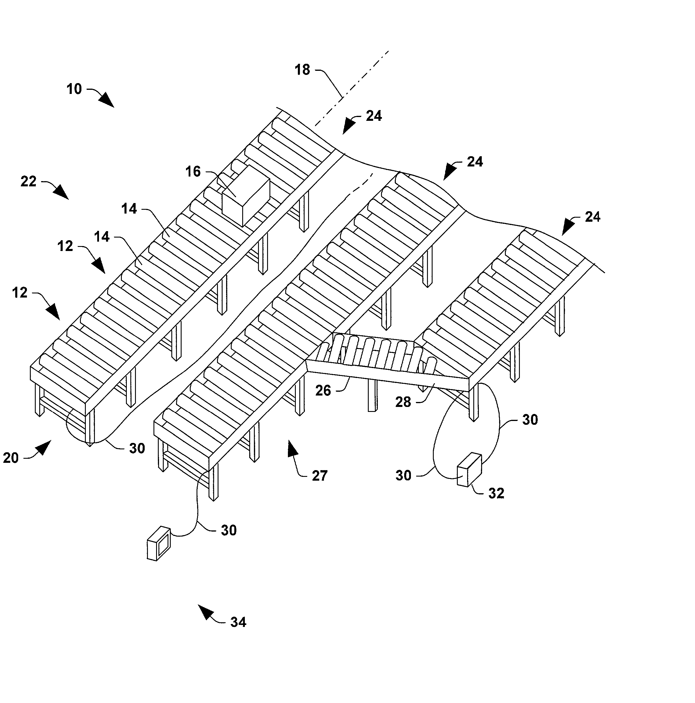
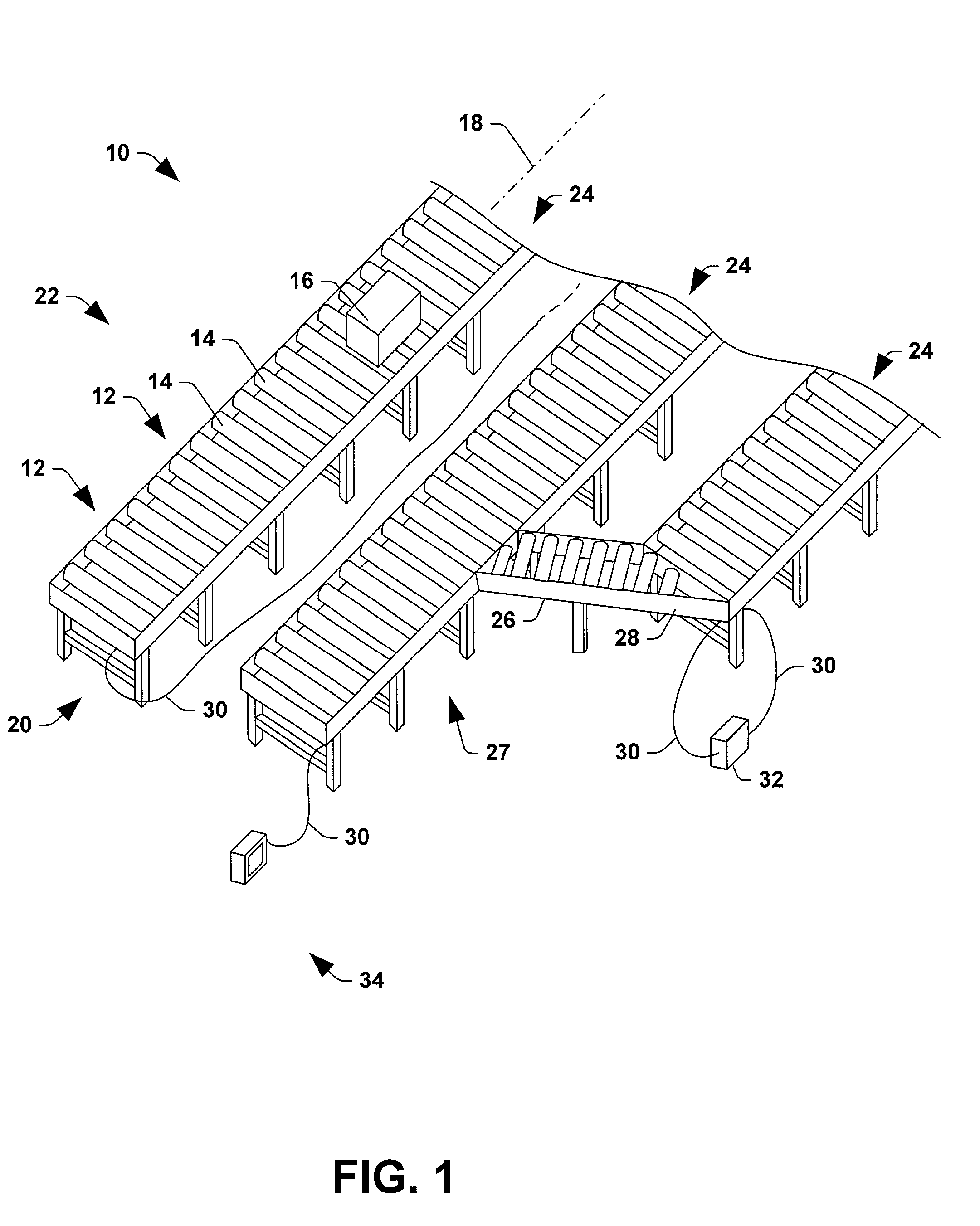
[0062] The present invention is now described with reference to the drawings, wherein like reference numerals are used to refer to like elements throughout. In order to provide context for the various features and aspects of the present invention, an exemplary conveyor system is illustrated and described. Referring now to FIG. 1, an exemplary conveyor system 10 may be assembled from a plurality of conveyor sticks 12, each providing upwardly exposed rollers 14 for moving one or more objects 16 along a conveyor axis 18. The rollers 14 of the conveyor sticks 12 may be reversible, thus allowing the object 16 to be moved in either direction along axis 18 in a controlled fashion. Nevertheless, an arbitrary "upstream" end 20 and "downstream" end 22 may be defined for each conveyor section representing one direction of flow along axis 18 for the processes of accumulation and slug release.

[0063] The conveyor sticks 12 may be arranged in one or more parallel banks 24 and may include alternati...


PUM


Abstract

A method and control system are provided for controlling a modular conveyor system, which may be networked together with other such systems in order to implement a control strategy for a modular conveyor system. The control system comprises a communications port for interconnection of the control system with a network for sending outgoing addressed data to other devices on the address-based network and for receiving incoming addressed data from other devices. The control system further comprises a logic system, which may receive a signal from an object sensor and provide a control signal or output adapted to control activation of a motorized roller assembly, based on an input signal from the object sensor or the communications port. The logic system may provide for single step operation whereby system troubleshooting may be facilitated, and in addition may provide situation aware and output value source selection functionality.

Description

CROSS-REFERENCE TO RELATED APPLICATIONS[0001] This application is a continuation-in-part of co-pending U.S. patent application Ser. Nos. 09 / 559,625 filed Apr. 27, 2000; 09 / 574,982 filed May 19, 2000; 09 / 644,635 filed Aug. 23, 2000; and 09 / 669,822 filed Sep. 26, 2000.TECHNICAL FIELD[0002] The present invention relates to the art of industrial controllers, and more particularly to systems and methods for controlling a modular conveyor.BACKGROUND OF THE INVENTION[0003] Industrial controllers are special purpose computers used for controlling industrial processes, manufacturing equipment, and other factory automation, such as conveyor systems. In accordance with a control program, the industrial controller measures one or more process variable or inputs reflecting the status of a controlled conveyor system, and changes outputs effecting control of the conveyor system. The inputs and outputs may be binary, (e.g., on or off), as well as analog inputs and outputs assuming a continuous rang...

Claims


Application Information

Patent Timeline
Patent Type & Authority Applications(United States)
IPC IPC(8): B65G37/02B65G43/08B65G43/10B65G47/26B65G47/31G05B19/418
CPCB65G37/02B65G43/08B65G43/10B65G47/261B65G47/31B65G2203/0233G05B19/4189G05B2219/31274Y02P90/02
Inventor WIELEBSKI, WAYNECASPERS, JOHN P.MAJCHER, GREGORY A.BLECH, STEVEN P.
Owner ROCKWELL TECH
Why Eureka
Try Eureka