Film-forming apparatus, method of cleaning the same, and method of manufacturing a light-emitting device

a film-forming apparatus and film-forming technology, applied in the direction of spray discharge apparatus, vacuum evaporation coating, coating, etc., can solve the problems of reducing throughput and inability to subject organic el materials to photolithography after

Inactive Publication Date: 2002-01-31
SEMICON ENERGY LAB CO LTD
View PDF1 Cites 105 Cited by
  • Summary
  • Abstract
  • Description
  • Claims
  • Application Information

AI Technical Summary

Problems solved by technology

Therefore, the organic EL material cannot be subjected to photolithography after being formed into a film.
However, there is a concern that water or oxygen adsorbed to the vapor-deposition mask and the adhesion preventing shield exposed to the atmosphere m

Method used


Image

  • Film-forming apparatus, method of cleaning the same, and method of manufacturing a light-emitting device
  • Film-forming apparatus, method of cleaning the same, and method of manufacturing a light-emitting device
  • Film-forming apparatus, method of cleaning the same, and method of manufacturing a light-emitting device

Examples


embodiment 1

[0039] In this embodiment, a method of cleaning a film-forming apparatus will be described, which is characterized in that equipments provided in a film-forming apparatus are irradiated with infrared light, UV-light, or visible light to sublimate a vapor-deposition material adhering to the equipments, and the sublimated vapor-deposition material is exhausted. The present example is one example of the present invention, and can cite the above description.

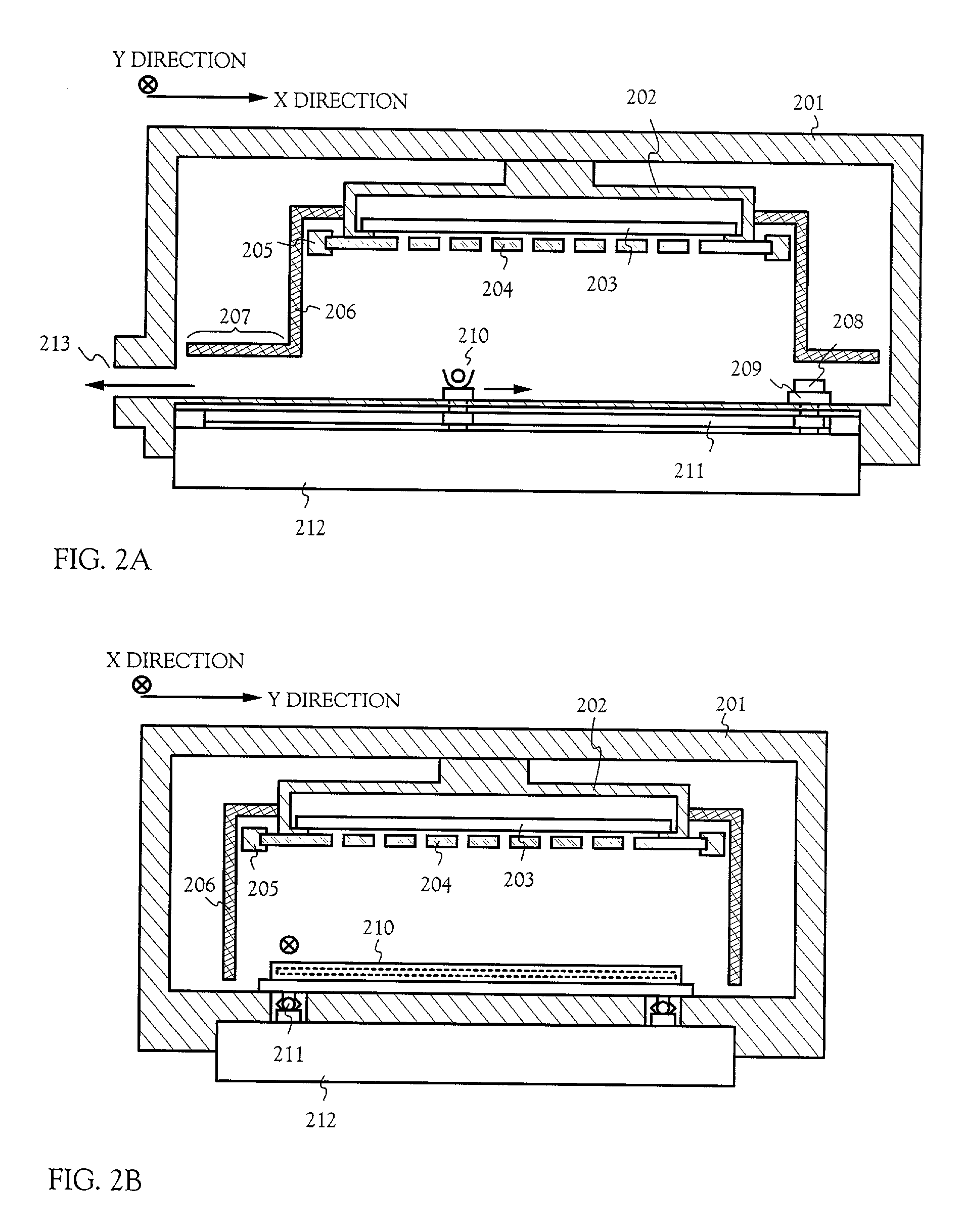
[0040] FIGS. 2A-2B show cross-sectional structures of a film-forming portion in a film-forming apparatus of this embodiment. FIGS. 2A and 2B show cross-sectional structures taken in directions vertical to each other. FIG. 2A shows a cross-section in an X-direction, and FIG. 2B shows a cross-section in a Y-direction. FIG. 4 is a top view of the film-forming portion in the film-forming apparatus of this embodiment.

[0041] In FIGS. 2A and 2B, a substrate holder 202 is provided in a film-forming chamber 201, and a substrate 203 is support...

embodiment 2

[0053] In this embodiment, a method of cleaning a film-forming apparatus will be described, which is characterized in that equipments provided in a film-forming chamber are heated with radiation heat to sublimate a vapor-deposition material adhering to the equipments, and the sublimated vapor-deposition material is exhausted. Radiation heat may be generated by flowing a current through a metal line (typically, a nichrome line) with high electrical resistance. Further, this embodiment is one example of the present invention, and can cite the above description.

[0054] FIGS. 5A-5B show cross-sectional structures of a film-forming portion in a film-forming apparatus of this embodiment. FIGS. 5A and 5B show cross-sectional structures taken in directions vertical to each other. FIG. 5A shows a cross-section in an X-direction, and FIG. 5B shows a cross-section in a Y-direction. Further, FIG. 6 is a top view of the film-forming portion in the film-forming apparatus of this embodiment.

[0055] ...

embodiment 3

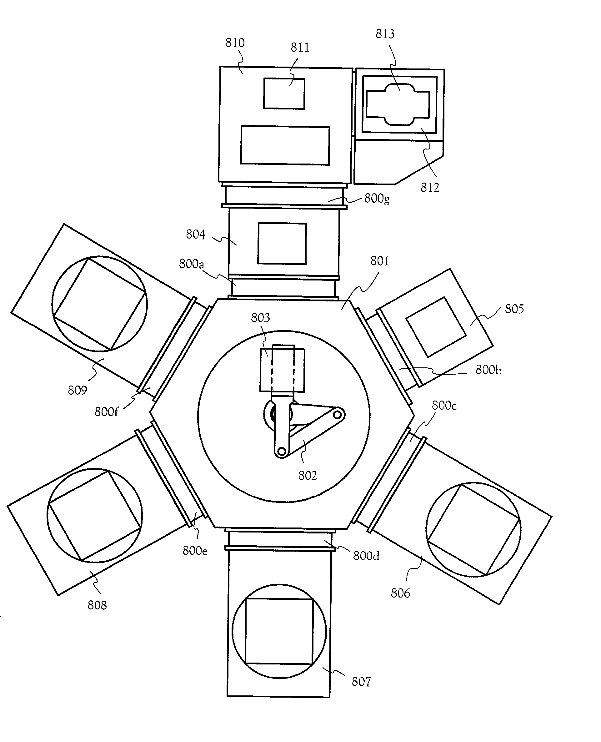
[0064] In this embodiment, a film-forming apparatus will be described in which an exhaust treatment chamber is connected to a film-forming chamber. In the film-forming apparatus of this embodiment shown in FIG. 7, a film-forming chamber 702 has the same structure as that shown in FIG. 2A, and an exhaust treatment chamber 701 is connected in series to the film-forming chamber 702. Thus, regarding the film-forming chamber 702, Embodiment 1 will be referred to, and the exhaust treatment chamber 701 will be mainly described.

[0065] In FIG. 7, the exhaust treatment chamber 701 is connected to the film-forming chamber 702 through a gate 703. The gate 703 plays a role in preventing exhaust gas from being mixed in the film-forming chamber 702 from the exhaust treatment chamber 701. Heating wires 704 are provided at a pipe in the vicinity of the gate 703, and the pipe 705 can be heated. The heating wires 704 are provided so as to prevent the vapor-deposition material exhausted from the film-f...


PUM

PropertyMeasurementUnit
Adhesion strengthaaaaaaaaaa

Abstract

A cleaning method of removing a vapor-deposition material adhering to equipments without exposure to the atmosphere is provided. A vapor-deposition material adhering to equipments (components of a film-forming apparatus) such as a substrate holder, a vapor-deposition mask, a mask holder, or an adhesion preventing shield provided in a film-forming chamber are subjected to heat treatment. Because of this, the adhering vapor-deposition material is re-sublimated, and removed by exhaust through a vacuum pump. By including such a cleaning method in the steps of manufacturing an electro-optical device, the manufacturing steps are shortened, and an electro-optical device with high reliability can be realized.

Description

TECHNICAL FIELD TO WHICH THE INVENTION BELONGS[0001] The present invention relates to a film-forming apparatus used for forming a film of a material (hereinafter, referred to as a "vapor-deposition material") that can be formed into a film by vapor deposition, a method of cleaning the same, and a method of manufacturing an electro-optical device using the cleaning method. In particular, the present invention is a technique effective in the case of using an organic material as a vapor-deposition material.[0002] In the present specification, an electro-optical device intends to include a solar battery, a CCD (charge coupled device), a CMOS sensor, a liquid crystal display apparatus, an EL display apparatus, or a light source including an EL element (these will be collectively referred to as a "light-emitting device").PRIOR ART[0003] In recent years, a light-emitting element (hereinafter, referred to as an "EL element") using an electro luminescent material (hereinafter, referred to as...

Claims


Application Information

Patent Timeline
IPC IPC(8): C23C14/56
CPCC23C14/564C23C14/04C23C14/54C23C14/243C23C14/12
Inventor YAMAZAKI, SHUNPEITAKAYAMA, TORUFUKUNAGA, TAKESHI
Owner SEMICON ENERGY LAB CO LTD
Why Eureka
Try Eureka