Eureka AIR delivers breakthrough ideas for toughest innovation challenges, trusted by R&D personnel around the world.

Device and method for controlling the amplitude of signals

Inactive Publication Date: 2002-02-21
NOKIA NETWORKS OY
View PDF4 Cites 5 Cited by
  • Summary
  • Abstract
  • Description
  • Claims
  • Application Information

AI Technical Summary

Problems solved by technology

If the amplitude of the signal input to the analogue to digital converter 30 is too high, then the converter 30 will become saturated, giving rise to phase errors, recovery time problems and unwanted noise.
In other words, if the signal is too small, it will be swamped by the noise floor and information carried by the signal may be lost.
One problem with the known architecture is that it is necessary to provide a receiver for each channel.
The need to provide a receiver for each channel increases substantially the costs of the base transceiver station.
Another problem with the known receiver is that it is necessary to use a SAW filter to filter out the adjacent channels and high power interferers which compromise the dynamic range of the converter 30.
SAW filters are expensive.

Method used


Image

  • Device and method for controlling the amplitude of signals
  • Device and method for controlling the amplitude of signals
  • Device and method for controlling the amplitude of signals

Examples


Embodiment Construction

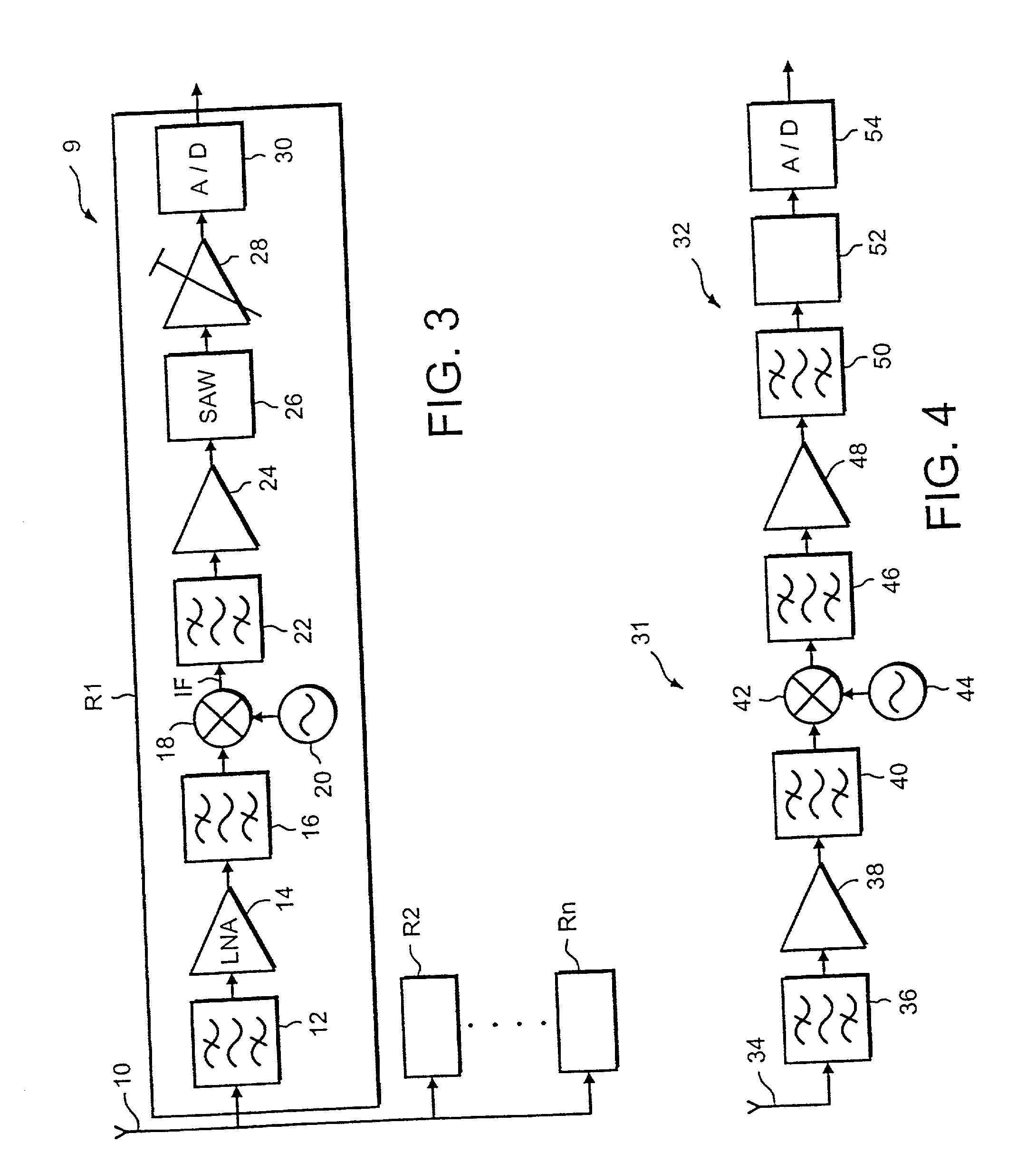
[0030] Reference will now be made to FIG. 4 which illustrates the receiver part 32 of a base transceiver station 31 embodying the present invention. Unlike the known base transceiver station, illustrated in FIG. 3, the base transceiver station 31 embodying the present invention only has a single receiver 32 which deals with all N channels to be received by the base transceiver station at the same time.

[0031] The receiving part 32 of the base transceiver station 31 comprises an antenna 34 which receives signals from the mobile stations in the cell associated with the base transceiver station. For the purposes of illustration, it will be assumed that the antenna 34 receives four channels CH1, CH2, CH3 and CH4 on frequencies F1, F2, F3 and F4 respectively. These channels are typically separated by at least 600 KHz. It should be appreciated that the base transceiver station 31 can of course receive more or less than 4 channels at the same time. For convenience, the embodiment of the pre...


PUM


Abstract

A device for ensuring that the amplitude of signals fall within a predetermined range, said device comprising input means for receiving a plurality of input signals at substantially the same time, a first path for increasing the amplitude of any of the input signals having an amplitude below a first threshold, a second path for decreasing the amplitude of any of the input signals having an amplitude which exceeds a second threshold and combining the outputs of the first and second paths to provide a plurality of signals having amplitudes between said first and second thresholds.

Description

[0001] The present invention relates to a device and method for ensuring that the amplitude of signals fall within a predetermined range.[0002] In particular, but not exclusively, the device and method can be used in a receiver for a wireless telecommunication network.BACKGROUND TO THE INVENTION[0003] FIG. 1 illustrates a known wireless telecommunication network 2. The area covered by the network 2 is divided into a number of cells 4. Each cell 4 has associated therewith a base transceiver station 6. Each base transceiver station 6 is arranged to communicate with the terminals 8 located in the cell 4 associated with that base transceiver station 6. The terminals 8 may be mobile stations which are able to move between the cells 4.[0004] Each base transceiver station is, in the GSM standard (Global System for Mobile Communications), arranged to receive N channels out of M available channels C1 . . . CM, as illustrated in FIG. 2a. The M channels C1 . . . CM occupy a bandwidth of XMHz. ...

Claims


Application Information

Patent Timeline
IPC IPC(8): H03G3/20
CPCH03G3/3078
Inventor ELLIOT, SEBASTIAN
Owner NOKIA NETWORKS OY
Why Eureka
Eureka Blog
Learn More