Toroidal choke inductor for wireless communication and control
What is Al technical title?
Al technical title is built by PatSnap Al team. It summarizes the technical point description of the patent document.
a technology of inductor and choke, which is applied in the direction of survey, sealing/packing, borehole/well accessories, etc., can solve the problems of high cost of method and system described in u.s. pat. no. 4,839,644 and the difficulty of using a cabl
Inactive Publication Date: 2002-03-28
SHELL OIL CO
View PDF0 Cites 128 Cited by
Summary
Abstract
Description
Claims
Application Information
AI Technical Summary
This helps you quickly interpret patents by identifying the three key elements:
Problems solved by technology
Method used
Benefits of technology
Problems solved by technology
It is undesirable and in practice difficult to use a cable along the tubing string either integral with the tubing string or spaced in the annulus between the tubing and the casing because of the number of failure mechanisms present in such a system.
But such standard electrical conduits can be difficult to route at great depths, around turns for deviated wells, along multiple branches for a well having multiple lateral branches, and / or in parallel with coil production tubing.
Therefore, the method and system described in U.S. Pat. No. 4,839,644 is expensive, has problems with brine leakage into the casing, and is difficult to use as a scheme for downhole two-way communication.
Other downhole communication schemes such as mud pulse telemetry (U.S. Pat. Nos. 4,648,471; 5,887,657 have shown successful communication at low data rates but are of limited usefulness as a communication scheme where high data rates are required or it is undesirable to have complex, mud pulse telemetry equipment downhole.
Such protection chokes work well for their intended purpose, but do not operate to define a power or communication circuit.
Method used
Image
Click on the blue label to locate the original text in one second.
Reading with bidirectional positioning of images and text.
Examples
first embodiment
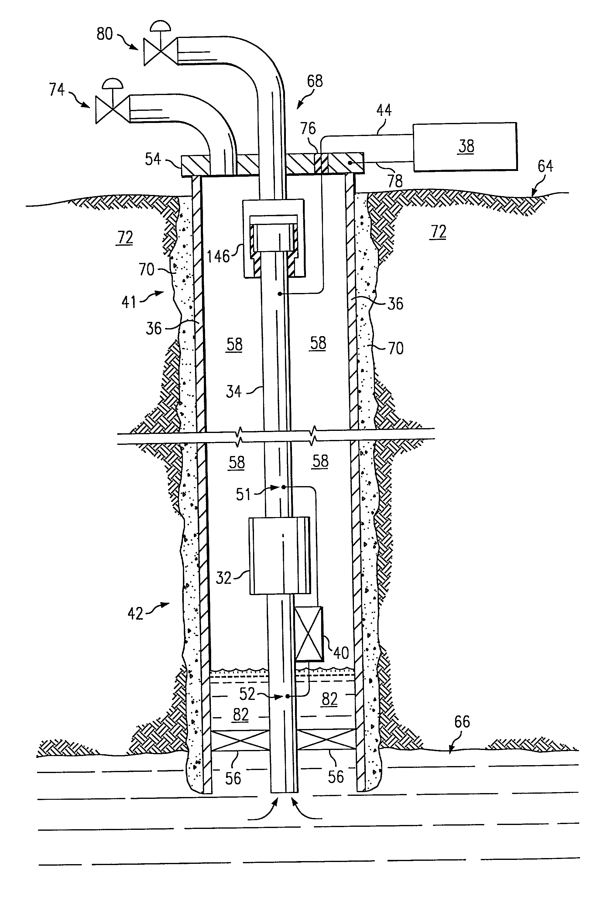
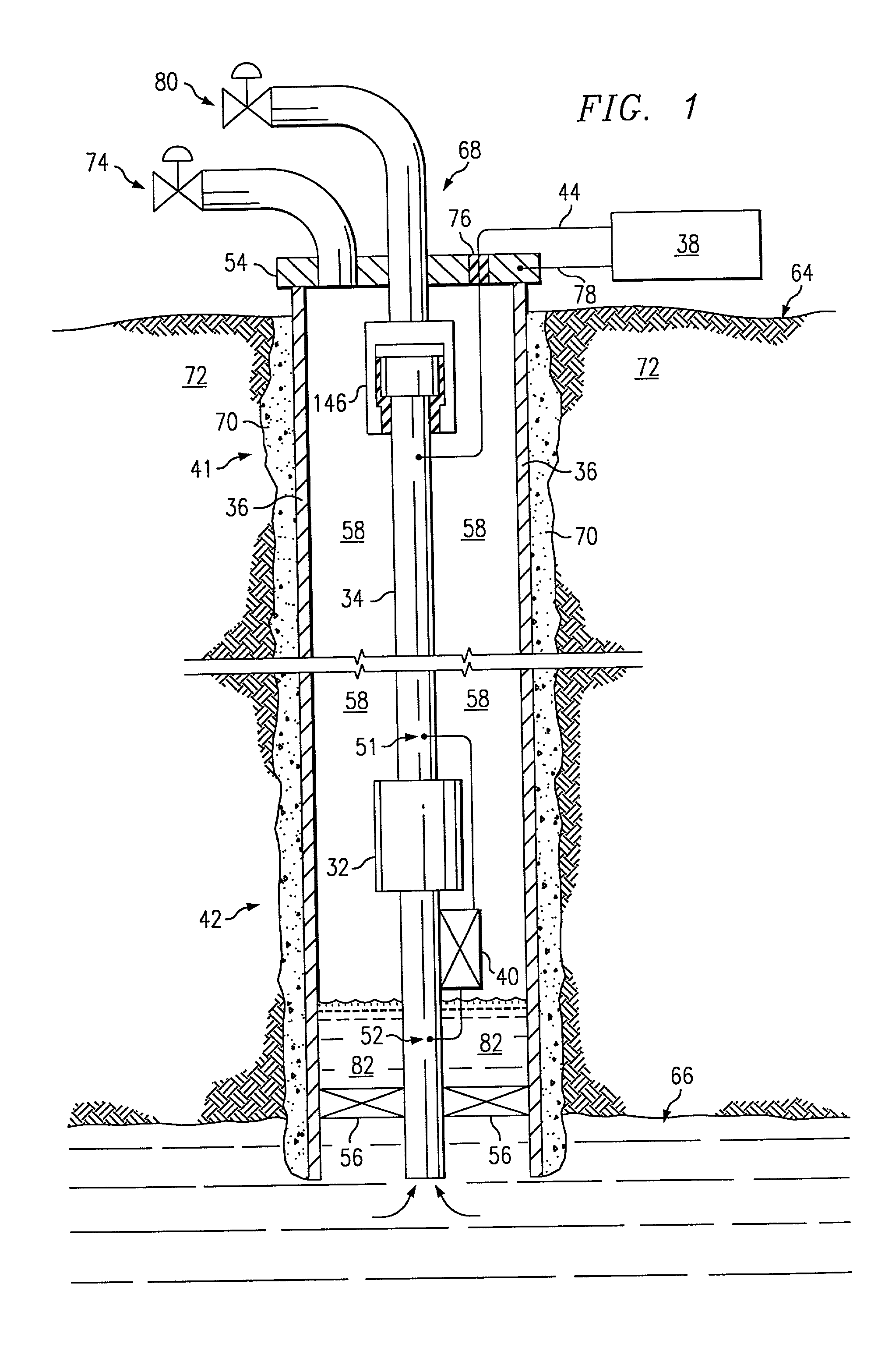
[0044] In the first embodiment shown in FIG. 1, the piping structure comprises a production tubing string 34 for a well, which is typically steel tubing. The system has an electrical impeding device 146 located about the tubing 34 along a first end 41 near the surface. Device 146 may consist of an electrically insulating joint as shown in FIG. 1, or an unpowered choke of the present invention. A lower choke 32 is located about the tubing along a second end 42 downhole within the well. The source of time-varying current 38 is electrically connected to the tubing 34 between the impeding devices 30, 32. The time-varying current can be alternating current (AC) or a varying direct current (DC), but AC is typically more practical in use. AC power and communications signals from the source 38 are connected by conductor 44 to the tubing 34 via an insulating feedthrough 76. The device 40 comprises two terminals 51, 52. A device terminal is defined generally as an electrical connection point ...
third embodiment
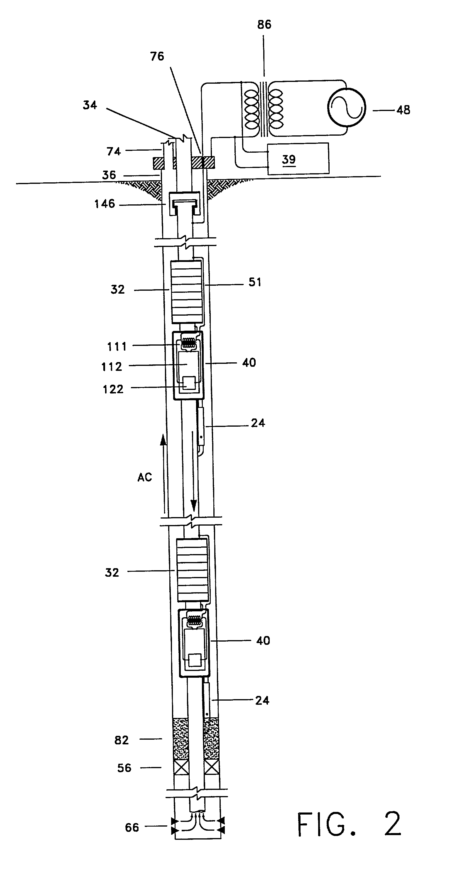
[0087] Each device 40 comprises a control module 110, sensors 120, a modem 122, an electric motor 124, and an electrically controllable valve 126. The control module 110 receives power and / or communications from the tubing 34, which it uses to provide power, control, and communications for the sensors 120, modem 122, and electric motor 124. The control module 110 can contain various logic structures for closed loop control of the valve 126 based on measurements taken by the sensors 120. In this example, there is a pressure sensor, a temperature sensor, and a flow sensor. However, other types of sensors 120 can also be used or substituted (e.g., acoustic sensor, chemical composition sensor). The modem 122 in the device 40 can send data from the sensors 120 to the computer system at the surface 64. Also, the modem 122 can receive control signals from the computer system via the modem in the source 38. The control module 110 provides power and control for the electric motor 124, which ...
PUM
Abstract
An induction choke in a petroleum well where a voltage potential is developed across the choke to power and communicate with devices and sensors in the well. Preferably, the induction choke is a ferromagnetic material and acts as an impedance to a time-varying current, e.g. AC. The petroleum well includes a cased wellbore having a tubing string positioned within and longitudinally extending within the casing. A controllable gas lift valve, sensor, or other device is coupled to the tubing. The valve sensor, or other device is powered and controlled from the surface. Communication signals and power are sent from the surface using the tubing, casing, or liner as the conductor with a casing or earth ground. For example, AC current is directed down a casing or tubing or a lateral where the current encounters a choke. The voltage potential developed across the choke is used to power electronic devices and sensors near the choke. Such induction chokes may be used in many other applications having an elongated conductor such as a pipe, where it is desirable to power or communicate with a valve, sensor, or other device without providing a dedicated power or communications cable.
Description
CROSS-REFERENCES TO RELATED APPLICATIONS[0001] This application claims the benefit of the U.S. Provisional Applications in the following table, all of which are hereby incorporated by reference:1 U.S. PROVISIONAL APPLICATIONS Serial T&K # Number Title Filing Date TH 1599 60 / 177,999 Toroidal Choke Inductor Jan. 24, 2000 for Wireless Communication and Control TH 1599x 60 / 186,376 Toroidal Choke Inductor Mar. 2, 2000 TH 1600 60 / 178,000 Ferromagnetic Choke in Jan. 24, 2000 Wellhead TH 1600x 60 / 186,380 Ferromagnetic Choke in Mar. 2, 2000 Wellhead TH 1601 60 / 186,505 Reservoir Production Mar. 2, 2000 Control from Intelligent Well Data TH 1602 60 / 178,001 Controllable Gas-Lift Well Jan. 24, 2000 and Valve TH 1603 60 / 177,883 Permanent, Downhole, Jan. 24, 2000 Wireless, Two-Way Telemetry Backbone Using Redundant Repeater, Spread Spectrum Arrays TH 1668 60 / 177,998 Petroleum Well Having Jan. 24 2000 Downhole Sensors, Communication, and Power TH 1669 60 / 177,997 System and Method for Jan. 24, 2000 ...
Claims
Application Information
Patent Timeline
Application Date:The date an application was filed.
Publication Date:The date a patent or application was officially published.
First Publication Date:The earliest publication date of a patent with the same application number.
Issue Date:Publication date of the patent grant document.
PCT Entry Date:The Entry date of PCT National Phase.
Estimated Expiry Date:The statutory expiry date of a patent right according to the Patent Law, and it is the longest term of protection that the patent right can achieve without the termination of the patent right due to other reasons(Term extension factor has been taken into account ).
Invalid Date:Actual expiry date is based on effective date or publication date of legal transaction data of invalid patent.
Patent Type & Authority Applications(United States)