Method and apparatus for determining blaster detonation time and first arrival time of seismic wave

a technology of blaster detonation time and seismic wave, which is applied in the direction of seismic signal recording, instruments, measurement devices, etc., can solve the problems of inability to accurately determine the detonation time, inability to mass produce seismic waves, and insufficient accuracy of detonation time acquisition, etc., to achieve the effect of low cost and convenient practi

Inactive Publication Date: 2002-03-28
CHINA PETROCHEMICAL CORP
View PDF0 Cites 4 Cited by
  • Summary
  • Abstract
  • Description
  • Claims
  • Application Information

AI Technical Summary

Benefits of technology

[0031] The object of the present invention is to provide a low cost, easy to practice method and a apparatus for detecting detonation time in industrial application to overcome the inaccuracy and expensive determination of measuring detonation time existing in the prior art.
[0032] It is another object of the present invention to provide a method and a apparatus for acquiring the first arrival time of seismic wave with reduced errors and high accuracy in real time to overcome the drawback of unreliability in acquisition of the first arrival time of seismic wave under the condition of using single detector.
[0037] The method used for measuring detonation time TB includes following steps: a)to measure current and voltage of the detonation circuit by the signal measuring means; b)to ignite the detonator with the high voltage detonation means and then to ignite the dynamite hole; c)the signal measuring means will detect current and voltage signal in the detonation circuit and transmit to the signal processing means; d)the signal processing means will calculate a general impedance curve by measuring its current and voltage, and by searching cycles of drastic changes of the curve to determine the detonation time TB. Furthermore, in order to smooth filter out noise and interference to enhance accuracy of measurement, a .omega.-frequency sine wave test signal has been added to the detonation circuit by is using a test-signal generating means in step a),and accordingly, in step d)the signal processing means will detect and measure current and voltage with same frequency as the .omega.-frequency test signal from current and voltage measured by the signal measuring means, and thus to compute the curve of impedance changes and, in some extent to eliminate noise and interference and to determine accurately the initial detonation time TB.

Problems solved by technology

The method and the apparatus used in the prior art have considerable limitation on the determination of the detonation time, the accurate detonation time can not be acquired properly.
This method is both scientific and accurate, without the detection of the signal being subjected to electromagnetic interference(Very strong electromagnetic occurs at ignition),while this method is very good, it is not appropriate for mass production of seismic waves due to its high cost of materials and complicated construction, the cost of which is too high in mass application.
It should also be noted that this method is subject to strong electromagnetic interference, the detonation time determined by which is not so accurate as the determined by the above-mentioned optical detection method.
As with the above-mentioned optical detection method, the construction cost in creases due to the increasing complexity of construction, the cost of which is also cost of which is also too high in mass application.
It can be seen that this method is rough, and thereby that is the limitation of this method which causes the under-improvement of the detonation time detecting method currently massively used in engineering.
If there is a relatively high error of the first arrival time tx of the reference recording track, the actual error will be increased.
The inflexion point approach applicable to single track recording is of a relatively high error, the max error thereof is up to 2.2 ms.

Method used


Image

  • Method and apparatus for determining blaster detonation time and first arrival time of seismic wave
  • Method and apparatus for determining blaster detonation time and first arrival time of seismic wave
  • Method and apparatus for determining blaster detonation time and first arrival time of seismic wave

Examples


Embodiment Construction

[0056] In following paragraphs along with drawings a more detailed description will be given for describing the present invention:

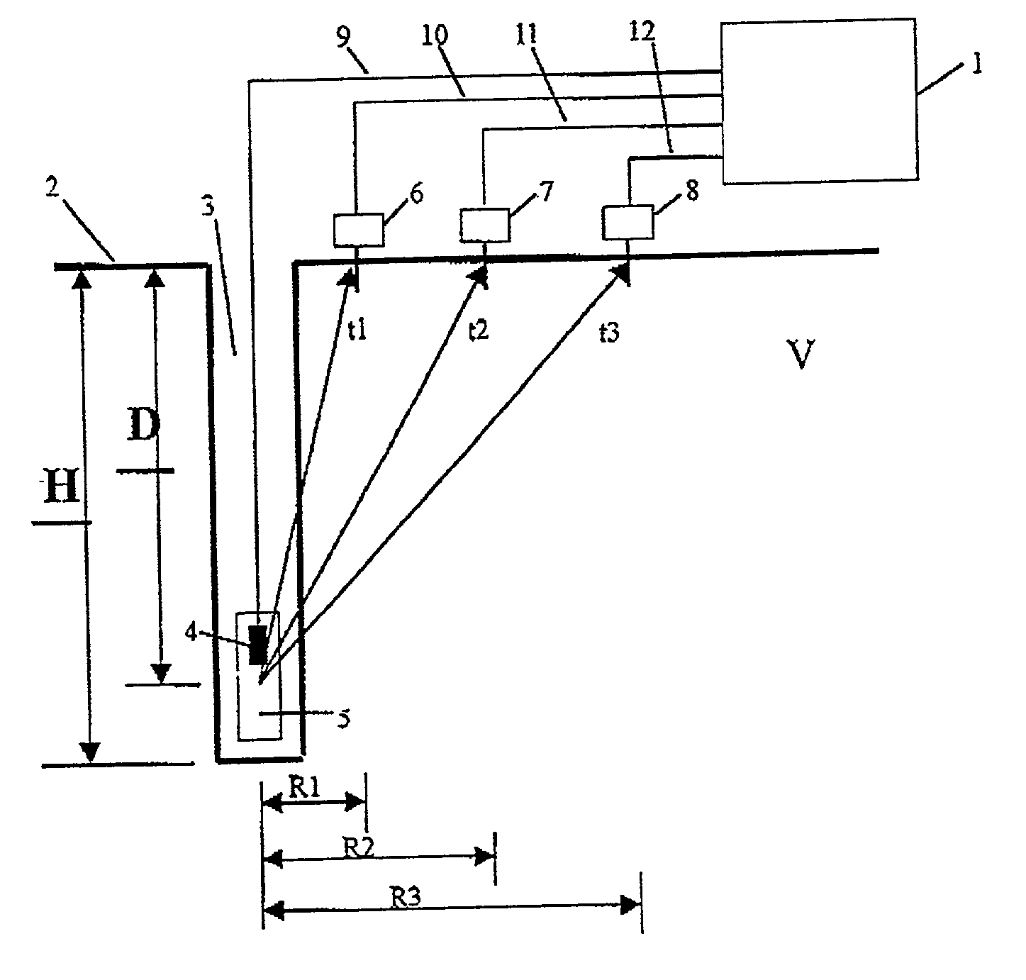
[0057] In FIG. 1 the means and the method described according the present invention were used for obtaining the propagation time and detonation depth. Dynamite pole 5 and detonator 4 as the source of seismic waves are placed in detonation hole 3, detonator 4 is placed in dynamite pole 5 which is linked via detonation line 9 to HV+ and HV- of the high voltage output outlet of blaster 1.

[0058] There are at least 3 detectors 6, 7, 8, in the surface 2 being perpendicular to the detonation hole. It is multi-point-detection line. All the detector are in one straight line of the same level. Every detector is connected to the blaster 1 respectively via wires 10, 11, 12. The distance R.sub.3 between uphole and the farthest detector station 8 is less than hole depth H.

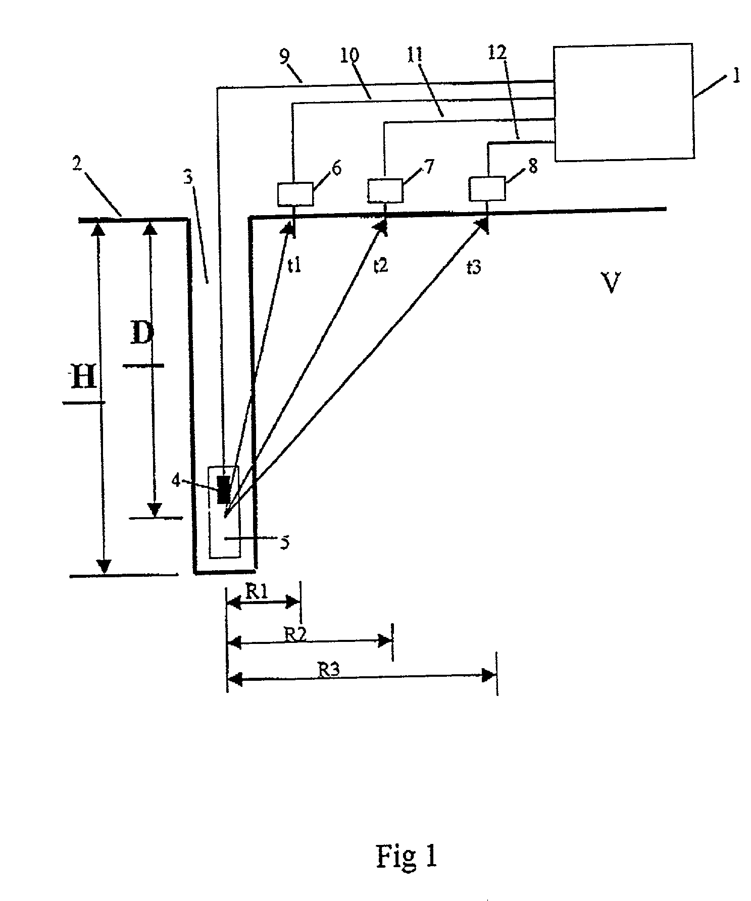
[0059] FIG. 2 is showing the means of the present invention used for determining detonation time, ...


PUM


Abstract

The present invention provides a apparatus and a method used for measuring the detonation time and the first arrival time of seismic waved caused in the seismic exploration field, wherein said apparatus includes a signal measuring means used for measuring current and voltage of the detonation circuit, a test signal generating means used for adding to the detonation circuit a omega-frequency sine wave test signal in order to smooth filter out noise and interference to enhance accuracy of measurement and a signal-processing means used for detecting and measuring current and voltage with same frequency as the omega-frequency test signal from current and voltage measured by the signal measuring means, and thus computing the curve of impedance changes and, in some extent to eliminate noise and interference and to determine accurately the detonation time TB. Said apparatus also include a or several detector used for measuring seismic waves and converting them to electrical signals, and a signal processing means connected to it. Wherein, the signal processing means carry out an average energy calculation on said electronic signal so as to determine whether the first arrival wave has arrived, and by using a set of smooth filtering method to compute accurately the first arrival time backward from the time of appearance of the first maximum value in the average energy curve after time ts. The above mentioned two signal processing means could be combined into a single one.

Description

[0001] The present invention relates to a method and an apparatus for accurately measuring propagation(traveling) time of the seismic wave, and more particularly, to a method and an apparatus for accurately determining the detonation time TB (also referred to as "time break") and the first arrival time(FAT) TR of the first arrival seismic wave(FASW) at the detonation uphole (or detonation point) in the field of seismic exploration.[0002] The method and the apparatus used in the prior art have considerable limitation on the determination of the detonation time, the accurate detonation time can not be acquired properly.[0003] It should be noted that the article "Optical fiber time break", GEOPHSICSV61,No. 1 , pp. 294-298,Jan.-Feb. 1996 (ISSN00168033),is worth notice. The technique revealed by this article and the method used therein are the insertion of a optical fiber into the explosive package with an end inserted into the explosive package as the signal detecting end to detect the ...

Claims


Application Information

Patent Timeline
Patent Type & Authority Applications(United States)
IPC IPC(8): G01V1/04G01V1/26
CPCG01V1/04G01V1/26
Inventor PENG, SHULINZHAO, WEIWEIWANG, LIXINLIU, XIAOXI
Owner CHINA PETROCHEMICAL CORP
Why Eureka
Try Eureka