Methods and computer readable medium for improved radiotherapy dosimetry planning

a technology of radiotherapy applied in the field of methods and computer readable medium for improving radiotherapy dosimetry planning, can solve the problems of limited geometric model generation, limited dosimetry planning for actual patients, and inaccuracy in modeling

Inactive Publication Date: 2002-04-18
BATTELLE ENERGY ALLIANCE LLC
View PDF25 Cites 41 Cited by
  • Summary
  • Abstract
  • Description
  • Claims
  • Application Information

AI Technical Summary

Benefits of technology

0017] It is, therefore, an object of the present invention to provide improved me

Problems solved by technology

Conventionally, however, the generation of geometric models has been limited because some methods do not base their information upon actual medical imagery.
With either method, inaccuracy in modeling occurs because all known information of a patient is n

Method used


Image

  • Methods and computer readable medium for improved radiotherapy dosimetry planning
  • Methods and computer readable medium for improved radiotherapy dosimetry planning
  • Methods and computer readable medium for improved radiotherapy dosimetry planning

Examples


example 2

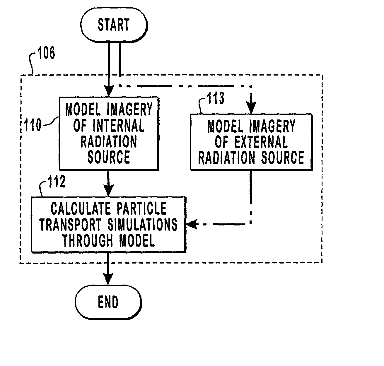
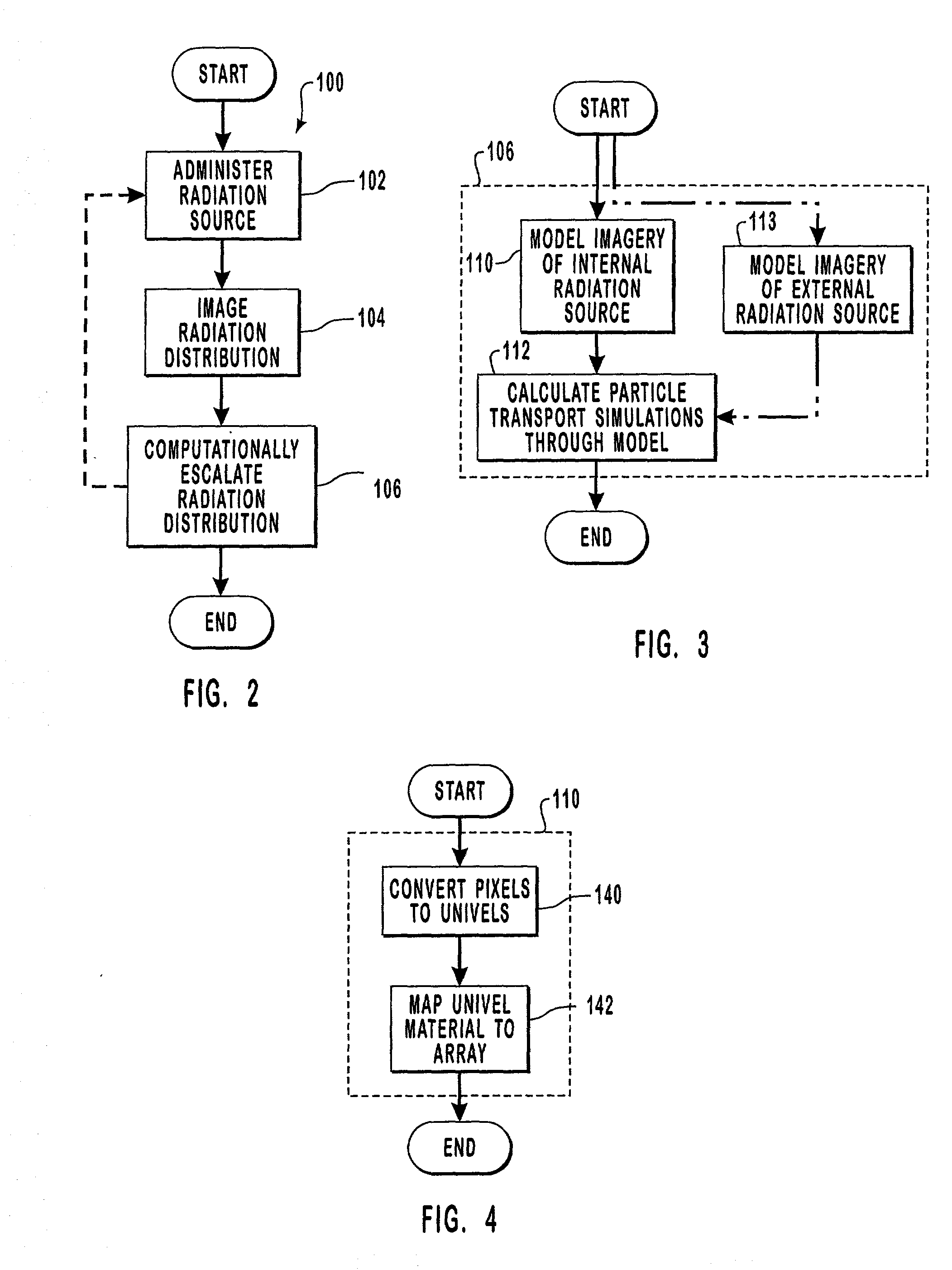
[0103] The following represents the actual algorithm information used to simulate such advanced particle transport along a particle track as presented at the 1998 Radiation Protection and Shielding Division Topical Conference in Nashville, Tenn. in April. Note that the subject matter of this presentation was directed only to external neutron sources.

[0104] Data Initialization

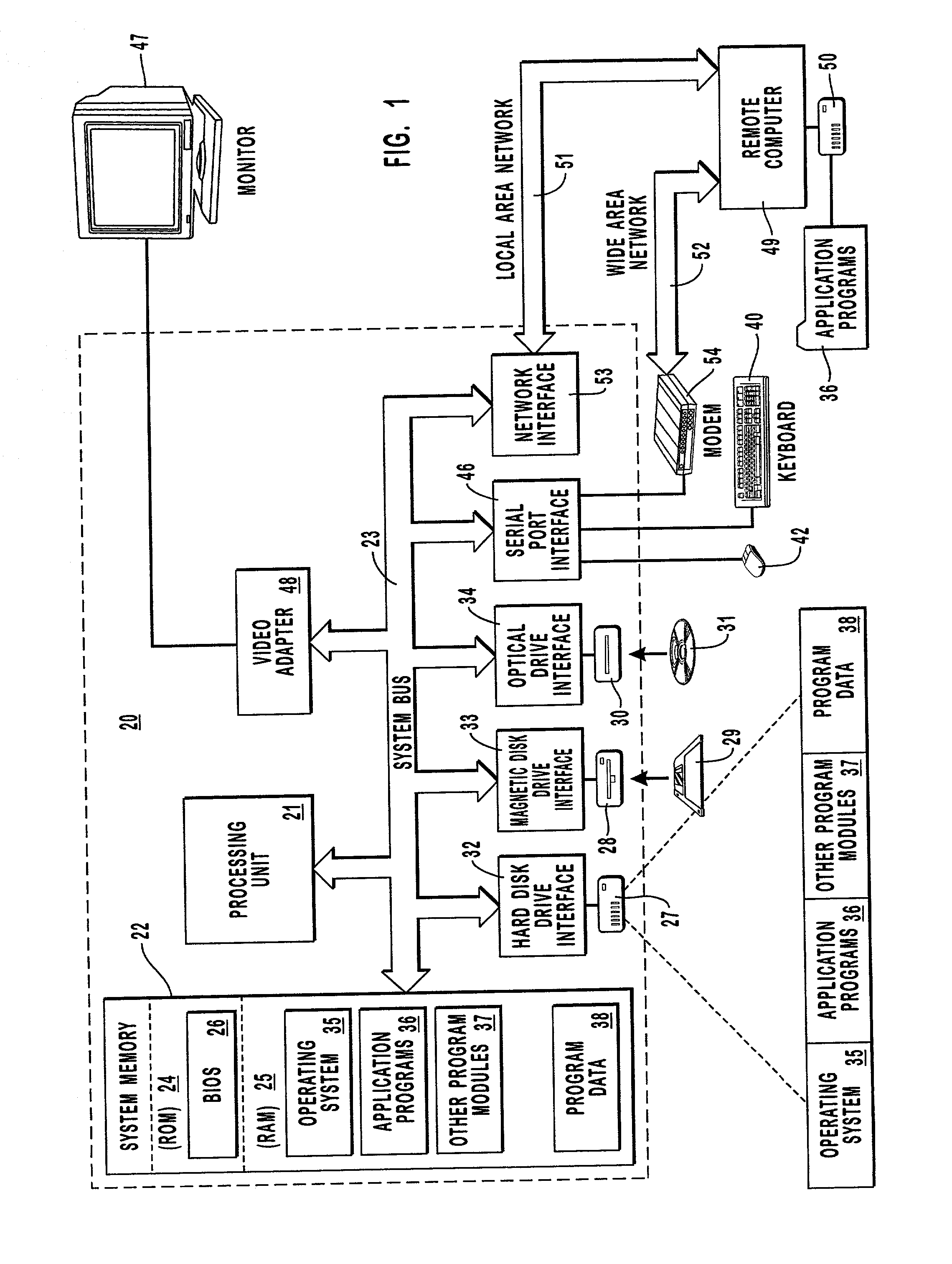
[0105] The uniformly spaced medical image data is read into an array. The x-pixel-size, y-pixel-size, and z-pixel size along with the minimum value of each coordinate is stored so conversions between world coordinates (WC) and normalized array coordinates (NAC) can be easily made. Here, the NAC simply corresponds to a location in the array of univels. For example, any location in the array can be found by an ordered triple of nonnegative integers, i.e., lookup (x,y,z)=array (z (width.times.length)+y (width)+.times.). A univel in WC is A mm.times.B mm.times.C mm. Whereas the univel in NAC is 1.times.1.times.1, fo...

example 3

[0112] The following data was presented at the 1998 conference in Nashville, Tenn. and is exemplary of a particle track having Y as a primary direction of movement, X is the secondary direction of movement increasing in 0.125 units of a Cartesian coordinate system and Z is the tertiary direction of movement increasing in 0.75 units. The initial starting position of the particle track after centering is x.sub.0=5.00, y.sub.0=1.5 and z.sub.0=10.125. Truncating (trunc) is the rounding down function. Stepping along the primary direction of movement yields the following data with an error term being an integer in the range of -32,768 to 32,767:

3 TABLE 2 x y z trunc(x) trunc(y) trunc(z) 5.000 1.5 10.125 5 1 10 5.125 2.5 10.875 5 2 10 5.250 3.5 11.625 5 3 11 5.375 4.5 12.375 5 4 12 5.500 5.5 13.125 5 5 13 5.625 6.5 13.875 5 6 13 5.750 7.5 14.625 5 7 14 5.875 8.5 15.375 5 8 15 6.000 9.5 16.125 6 9 16

[0113] The bulk of the corresponding stepping algorithm for this example is as follows:


PUM


Abstract

Methods and computer readable media are disclosed for ultimately developing a dosimetry plan for a treatment volume irradiated during radiation therapy with a radiation source concentrated internally within a patient or incident from an external beam. The dosimetry plan is available in near"real-time" because of the novel geometric model construction of the treatment volume which in turn allows for rapid calculations to be performed for simulated movements of particles along particle tracks therethrough. The particles are exemplary representations of alpha, beta or gamma emissions emanating from an internal radiation source during various radiotherapies, such as brachytherapy or targeted radionuclide therapy, or they are exemplary representations of high-energy photons, electrons, protons or other ionizing particles incident on the treatment volume from an external source. In a preferred embodiment, a medical image of a treatment volume irradiated during radiotherapy having a plurality of pixels of information is obtained.

Description

[0001] This application claims priority from U.S. Provisional Application Ser. No. 60 / 191,079 filed Mar. 21, 2000, which is a continuation-in-part of U.S. application Ser. No. 09 / 063,736, filed Apr. 21, 1998, which are incorporated herein by reference.[0003] Field of the Invention[0004] The present invention relates generally to radiation therapy and specifically to the dosimetric planning thereof. More specifically, the present invention relates to the macrodosimetry planning for specific radiotherapies, such as targeted radionuclides and brachytherapy, having radiation sources concentrated internally within a patient, as well as to external-beam photon radiotherapy. Even more specifically, the present invention relates to methods and computer readable medium for computationally enlarging the dose distributions of a treatment volume irradiated during various therapies.[0005] Copyrighted Materials[0006] A portion of the disclosure of this patent document contains materials to which ...

Claims


Application Information

Patent Timeline
IPC IPC(8): A61M36/00A61N5/10G06F19/00
CPCA61N5/1001A61N5/1027A61N5/1031G06F19/3487G06F19/3437G06F19/3456G06F19/3481A61N2005/1034G16H50/50G16H15/00G16H20/40
Inventor WESSOL, DANIEL E.FRANDSEN, MICHAEL W.WHEELER, FLOYD J.NIGG, DAVID W.
Owner BATTELLE ENERGY ALLIANCE LLC
Why Eureka
Try Eureka