Support plinth for a power diode in a motor vehicle alternator

a technology for motor vehicles and power diodes, which is applied in the direction of dynamo-electric components, solid-state devices, associations for rectification, etc., can solve the problem that the handling operation is in general a very delicate one, and achieve the effect of convenient fitting of the diod

Inactive Publication Date: 2002-04-25
VALEO EQUIP ELECTRIC MOTEUR
View PDF1 Cites 8 Cited by
  • Summary
  • Abstract
  • Description
  • Claims
  • Application Information

AI Technical Summary

Benefits of technology

0003] One object of the invention is to make it easier to fit th

Problems solved by technology

However, this handling operation is in general a very delicate one to carry out, because

Method used


Image

  • Support plinth for a power diode in a motor vehicle alternator
  • Support plinth for a power diode in a motor vehicle alternator

Examples


Embodiment Construction

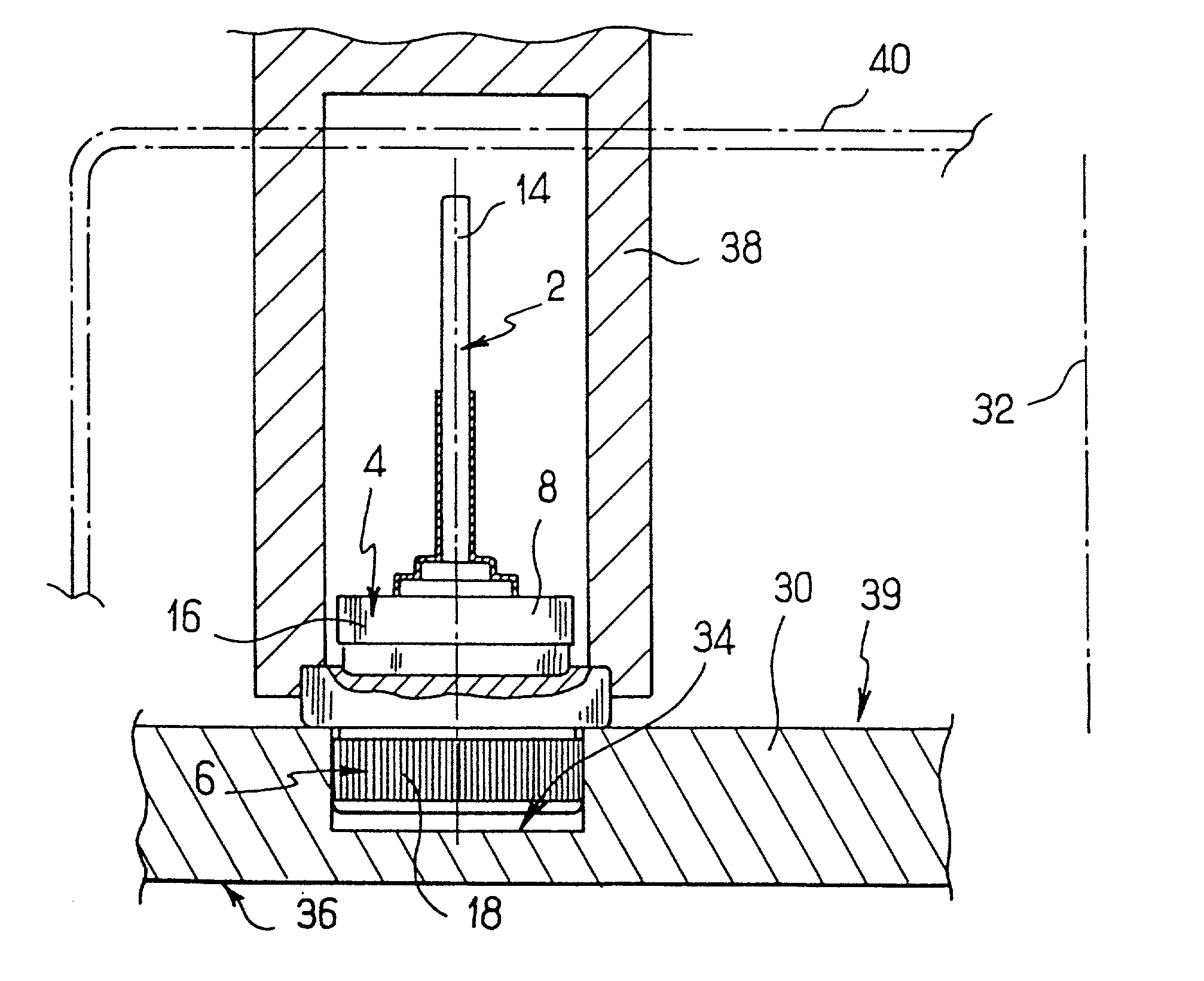
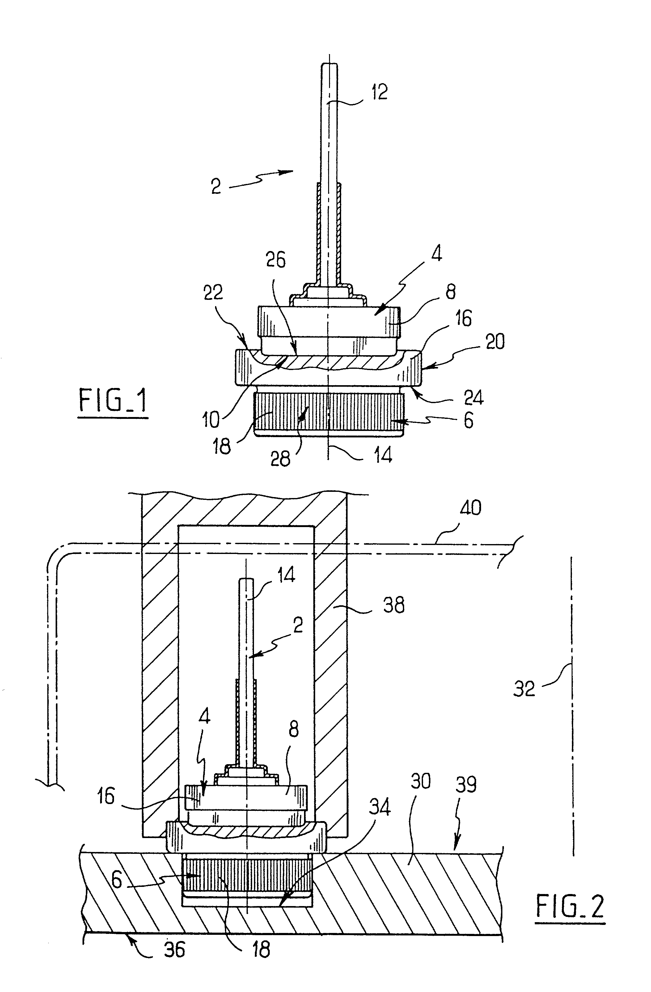
[0014] With reference to FIG. 1, the assembly 2 in this embodiment of the invention comprises a diode 4 and a support base or plinth 6. The diode 4 is a conventional power diode adapted to be welded (or soldered) in place. It comprises a metallic housing 8 which encloses a semiconductor component. The housing 8 defines a form of revolution about an axis of symmetry, and has a flat circular face 10, which in this example is its lower face and which constitutes a connecting terminal for the diode. The diode has another connecting terminal 12, which is elongate in form and coaxial with the housing 8, the terminal 12 being opposed to the face 10 in the axial direction.

[0015] The plinth 6 is symmetrical as a body of revolution about an axis 14. It comprises an abutment portion 16 and a plug portion 18, each of which is in the form of a thick disc. The plinth is made of an electrically conductive metal, and consists of a single piece.

[0016] The abutment portion 16 has a cylindrical side f...


PUM


Abstract

A motor vehicle alternator includes a support having a hole which receives a plug portion of a support plinth on which a power diode is welded or soldered, the plinth having an axis along which it is force-fitted in the hole. The plinth also has an abutment portion projecting radially from the plug portion with respect to the axis.

Description

[0001] This invention relates to plinths for supporting mounting diodes, in particular power diodes constituting a rectifier bridge, in a machine such as an alternator, especially for motor vehicles.[0002] It is known from French patent specification No. FR 2 737 618A to mount a diode on a support plinth or base which is generally in the form of a thick disc. One end of the diode is welded (or soldered) to one face of the plinth. The plinth is then force-fitted into a hole in a heat sink, or dissipator, of an alternator, from one side of the heat sink that faces towards the stator of the alternator, with the diode being finally disposed on a side of the dissipator which is opposite to the stator. This arrangement of diode and plinth has the advantage that it is thus possible to fix diodes at will to the same heat sink, whether they are adapted for either direct force-fitting, or for welding (soldering), the diodes having in the latter case been previously secured to a support plinth...

Claims


Application Information

Patent Timeline
IPC IPC(8): H01L25/11H02K11/04
CPCH02K11/046H01L25/115H01L24/01H02K11/05
Inventor GAUTIER, JEAN
Owner VALEO EQUIP ELECTRIC MOTEUR
Why Eureka
Try Eureka