Dentition image reading apparatus

a reading apparatus and image technology, applied in the field of reading apparatus for reading images, can solve the problems of difficult reduction of production costs, inability to recognize the relationship between the treatment-requiring portion and the normal portion, and inability to recognize the treatment-requiring portion

Inactive Publication Date: 2002-05-16
ORANGE HOUSE CO LTD
View PDF0 Cites 35 Cited by
  • Summary
  • Abstract
  • Description
  • Claims
  • Application Information

AI Technical Summary

Benefits of technology

[0016] Accordingly, the external shape, evenness, color and dimension of the tooth can be facilitated, which enables to determine treatment, record growth of a child, determine whether orthodontics is required or not, and determine whether orthodontics wiring is required or not in a quantitative manner, and further, enables to efficiently collect dentition image at a mass check-up.
[0017] Especially, since only the light source and the reflection mirror are accommodated in the hollow portion of the in-mouth insert to be inserted to mouth, the size thereof can be reduced as compared to a conventional arrangement having a transparent container accommodating the image sensor and the light source. Further, since the image is obtained by receiving light reflected by the reflection mirror by the image pick-up optical system, the production cost can be reduced as compared to the conventional image pick-up device having a deflecting device.
[0021] In the present invention, the image pick-up optical system may preferably include: an image sensor; a lens for forming an image of the light reflected by the reflection mirror on a light-receiving surface of the image sensor; and a light-shield provided between the lens and the reflection mirror for preventing the light from the light source from directly entering into the image sensor.
[0022] According to the above arrangement, since the image pick-up optical system has the image sensor and the lens for focusing the light reflected by the reflection mirror on the light-receiving surface of the image sensor and the light-shield is disposed between the lens and the reflection mirror, the light directly entering from the light source into the image sensor can be removed to the utmost, thereby obtaining more vivid image.
[0024] According to the above arrangement, since the scanning base having the light source and the reflection mirror at a distal end thereof and having the image pick-up optical system at a base end thereof is movably guided along the depth direction of the hollow portion of the in-mouth insert and is moved for a predetermined pitch by the drive unit, the dentition image in mouth can be accurately obtained for every predetermined pitch.
[0026] According to the above arrangement, since the light-transmitting portions are respectively provided on the front and back sides of the in-mouth insert and the image pick-up optics have the light source inserted in the hollow portion in the in-mouth insert for irradiating light on the upper jaw dentition and the lower jaw dentition through the light-transmitting portions and a pair of reflection mirrors for reflecting the light from the upper jaw dentition and the lower jaw dentition toward the outside of the in-mouth insert, the upper jaw dentition and the lower jaw dentition can be simultaneously taken by a single scan. Further, since the positional relationship between the upper jaw dentition and the lower jaw dentition can be accurately obtained, the positional relationship between the upper and lower bite surfaces can be accurately grasped.

Problems solved by technology

However, since the above apparatuses only partially take a picture of the tooth to be treated and the image of the entire dentition cannot be taken, a treatment-requiring portion, and relationship between the treatment-requiring portion and the normal portion cannot be recognized.
However, former method for obtaining the entire image of the dentition, the "measuring method of in-mouth space and an apparatus for implementing the method", requires a deflecting device of complicated structure and production cost thereof is difficult to be reduced.
Further, since the latter "dentition image reading apparatus" accommodates the image sensor and the light source within the transparent container inserted into mouth, the size of the transparent container is increased and therefore is difficult to be used for a child.

Method used


Image

  • Dentition image reading apparatus
  • Dentition image reading apparatus
  • Dentition image reading apparatus

Examples


first embodiment

[0037] [First Embodiment]

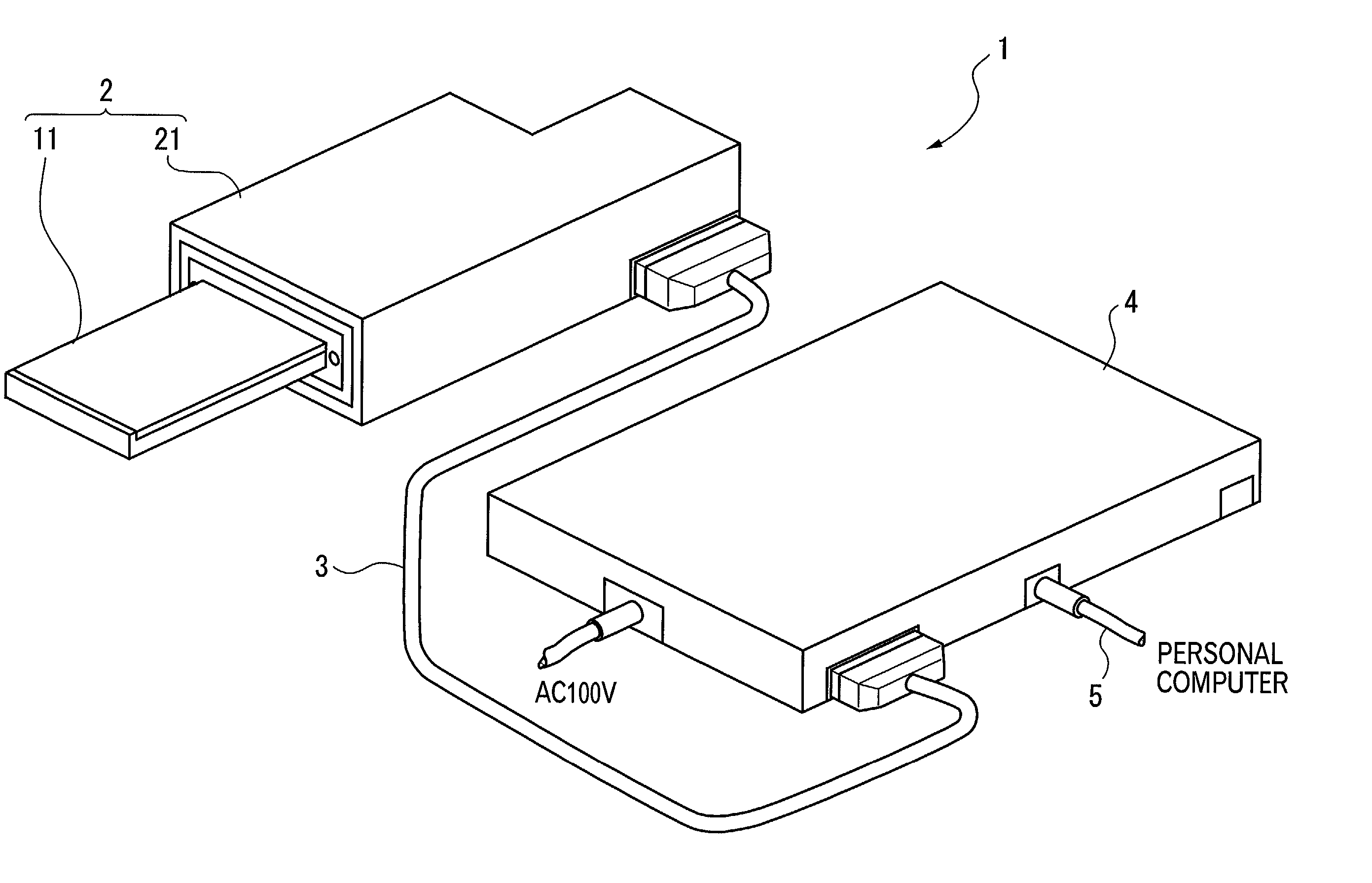
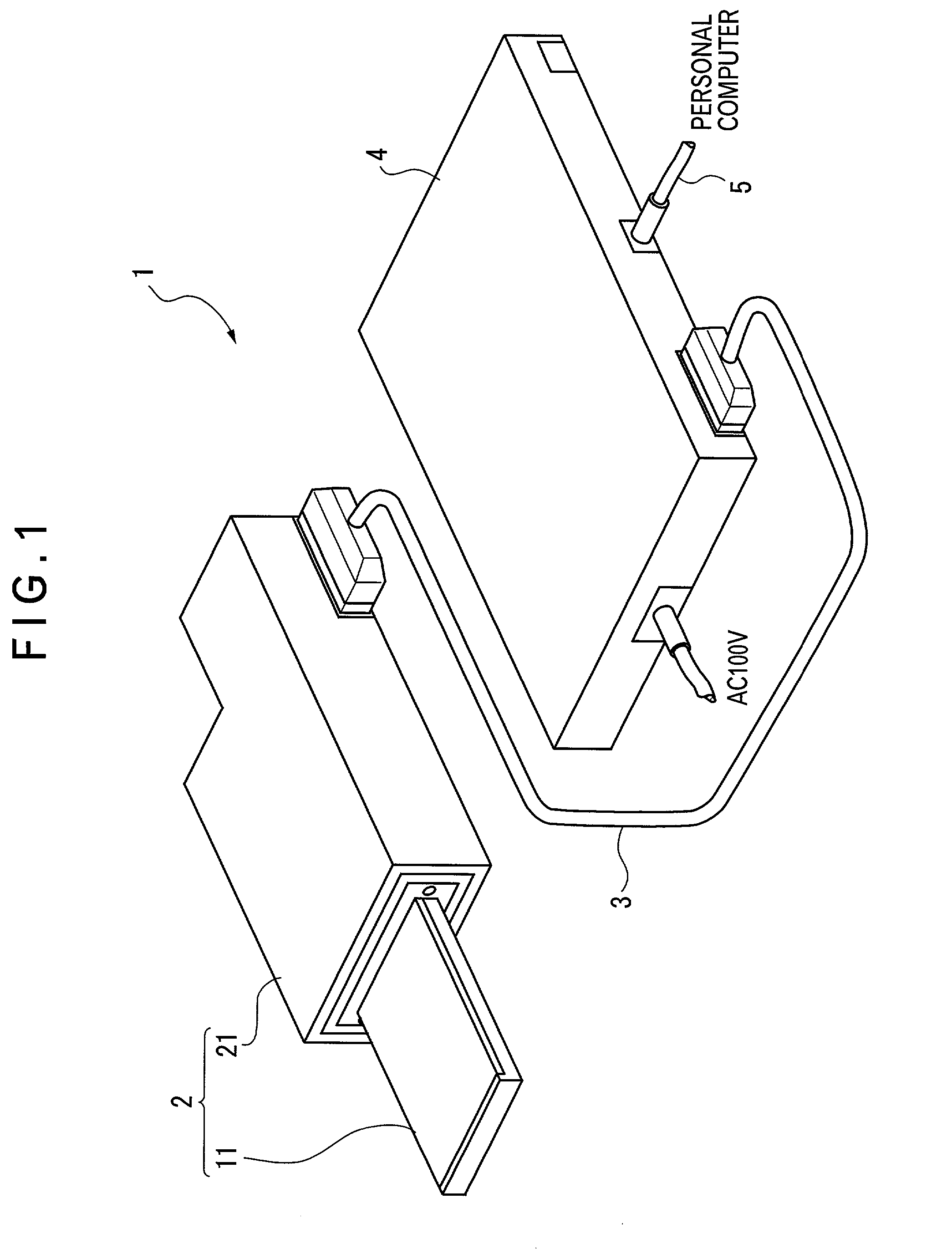
[0038] First embodiment of the present invention is shown in FIGS. 1 to 6. As shown in FIG. 1, the dentition image reading apparatus 1 of the present embodiment includes a dentition image pick-up device 2 and a power source 4 connected to the dentition image pick-up device 2 through a connection cable 3. A personal computer (not shown) constituting a below-described image processing unit is connected to the power source 4 through a USB cable 5.

[0039] The dentition image pick-up device 2 includes an in-mouth insert 11 inserted into a mouth having an upper jaw dentition and a lower jaw dentition, and image pick-up optics 21.

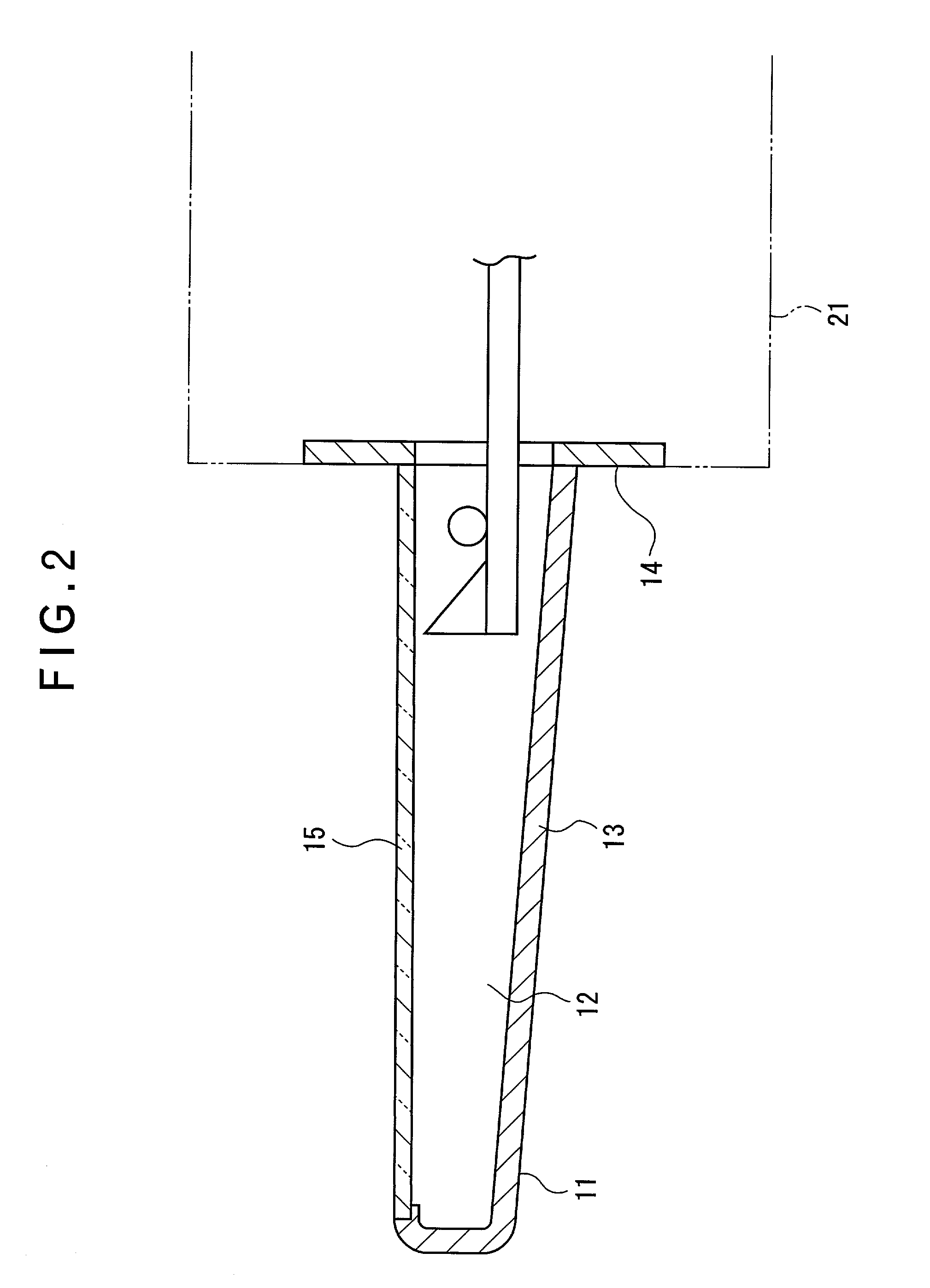
[0040] As shown in FIG. 2, the in-mouth insert 11 is of width and thickness capable of being inserted into mouth, which includes a flat square insert tube 13 having a hollow portion 12 thereinside and a fringe 14 integrated with the base end of the insert tube 13 and attached to the image pick-up optics 21. A light-transmitting portion 15 i...

second embodiment

[0061] [Second Embodiment]

[0062] FIG. 7 shows a second embodiment. The dentition image reading apparatus according to the present embodiment has shorter light path length than the first embodiment by shortening the focus distance of the lens 45, thereby omitting mirrors 42, 43 and 44.

[0063] Further, the present embodiment differs from the first embodiment in that the two light-shield plates 49A and 49B are disposed sandwiching the light path between the reflection mirror 23 and the lens 45.

third embodiment

[0064] [Third Embodiment]

[0065] FIG. 8 shows a third embodiment. The dentition image reading apparatus of the present embodiment differs from the second embodiment in that a slant angle adjuster 71 for adjusting the slant angle of the reflection mirror 23 is added.

[0066] The slant angle adjuster 71 is composed of a leaf spring 72 cut and raised from the scanning base 32 and attached with the reflection mirror 23, and an inclination adjuster 73 movable toward and away from the leaf spring 72 provided between the reflection mirror 23 and the scanning base 32.

[0067] According to the above arrangement, when the inclination adjuster 73 is moved toward and away from the leaf spring 72, the leaf spring 72 is bent in accordance with the position thereof, thus changing the slant angle of the reflection mirror 23. Then, though the light reflecting right below or just above the dentition enters into the color CCD 46 through the reflection mirror 23 in the conventional arrangement, the light re...


PUM


Abstract

A dentition image reading apparatus (1) includes an in-mouth insert (11) to be inserted into mouth and image pick-up optics (21), the in-mouth insert including a light-transmitting portion (15) at least on one of front and back sides and a hollow portion (12) provided thereinside, the image pick-up optics (21) including: a light source (22) inserted in the hollow portion of the in-mouth insert for irradiating light on the dentition through the light-transmitting portion; a reflection mirror (23) for reflecting the light from the dentition toward the outside of the in-mouth insert; a scanner 31 for moving the light source and the reflection mirror along the depth direction of the hollow portion of the in-mouth insert; and an image pick-up optical system (41) for receiving the light reflected by the reflection mirror.

Description

[0001] 1. Field of the Invention[0002] The present invention relates to a dentition image reading apparatus. More specifically, it relates to a dentition image reading apparatus for directly taking a picture of upper jaw dentition and lower jaw dentition from inside of mouth to obtain an entire image of the dentition.[0003] 2.Description of Related Art[0004] Conventionally, a roentgenography has been widely used as an indispensable tool for obtaining image in dental medical treatment. However, in recent years, digital cameras and small CCD cameras have come to be used for the purpose of explaining to a patient.[0005] For instance, an image pick-up device having a hand holder including an image sensor and optical fibers arranged in ring-shape around the image sensor has been proposed in Japanese Utility Model Application Publication No. Hei 6-28859.[0006] In Japanese Patent Laid-Open Publication No. Hei 9-140664, a dental in-mouth observation camera having a light guide and a CCD sen...

Claims


Application Information

Patent Timeline
Patent Type & Authority Applications(United States)
IPC IPC(8): A61C19/04A61B1/04A61B1/24A61B1/247G06T1/00
CPCA61B1/247
Inventor SUGIMOTO, YUKITERU
Owner ORANGE HOUSE CO LTD
Why Eureka
Try Eureka