

Lithographic apparatus, integrated circuit device manufacturing method, and integrated circuit device manufactured thereby
a technology of integrated circuit devices and lithographic projection devices, which is applied in the direction of instruments, radiation therapy, therapy, etc., can solve the problems of not all variations in absorption are easily or accurately predictable, and the exposure intensity profile will cross the resist threshold at the wrong point, and the variation is significant and unpredictabl
- Summary
- Abstract
- Description
- Claims
- Application Information
AI Technical Summary
Problems solved by technology
Method used
Image

Examples
embodiment 1
[0038] Embodiment 1
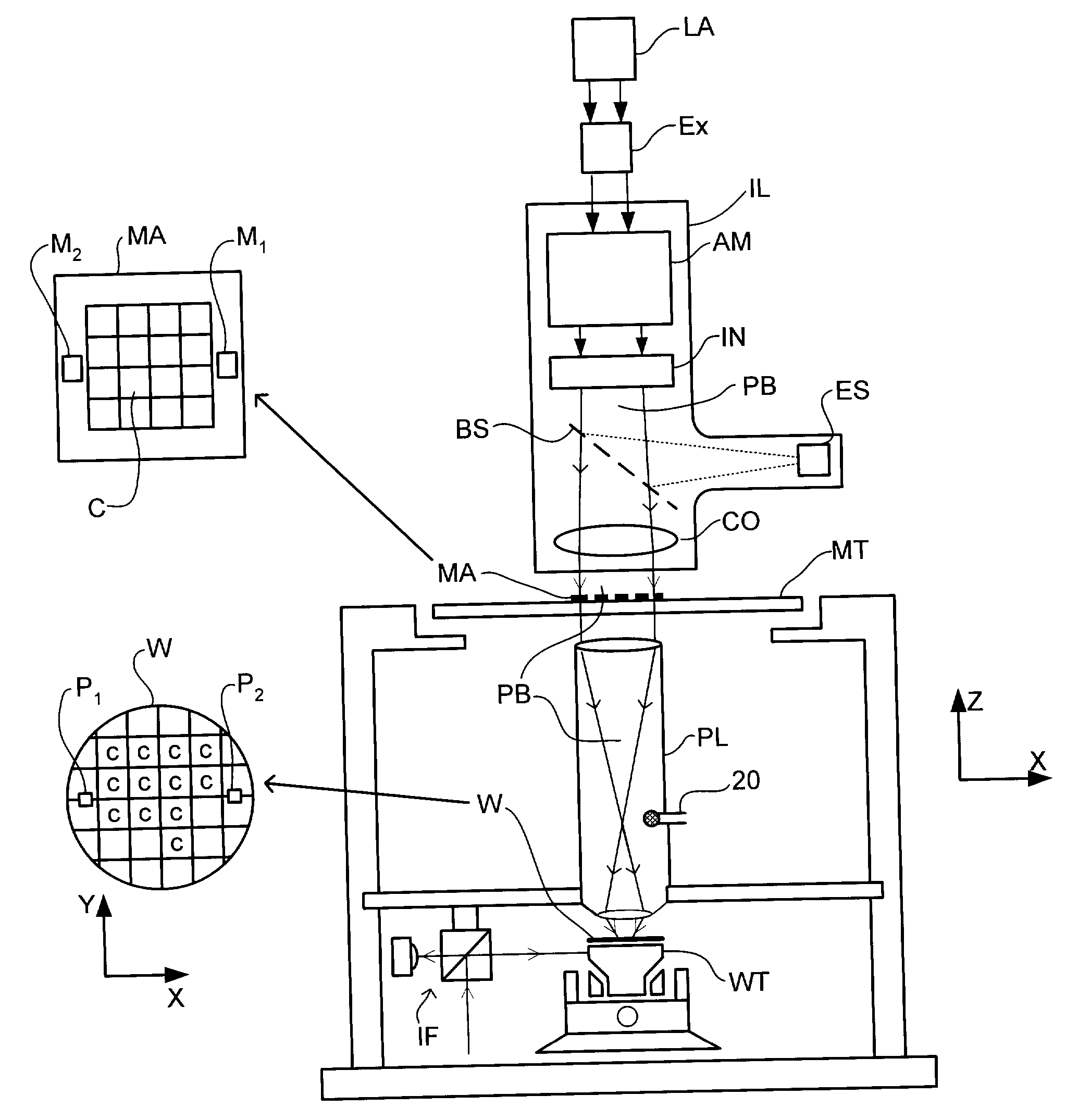
[0039] FIG. 1 schematically depicts a lithographic projection apparatus according to a particular embodiment of the invention. The apparatus comprises:
[0040] a radiation system Ex, IL, for supplying a projection beam PB of pulsed radiation (e.g. UV radiation such as for example generated by an excimer laser operating at a wavelength of 193 nm or 157 nm, or by a laser-fired plasma source operating at 13.6 nm). In this particular case, the radiation system also comprises a radiation source LA;
[0041] a first object table (mask table) MT provided with a mask holder for holding a mask MA (e.g. a reticle), and connected to first positioning means for accurately positioning the mask with respect to item PL;
[0042] a second object table (substrate table) WT provided with a substrate holder for holding a substrate W (e.g. a resist-coated silicon wafer), and connected to second positioning means for accurately positioning the substrate with respect to item PL;
[0043] a projec...
embodiment 2
[0057] Embodiment 2
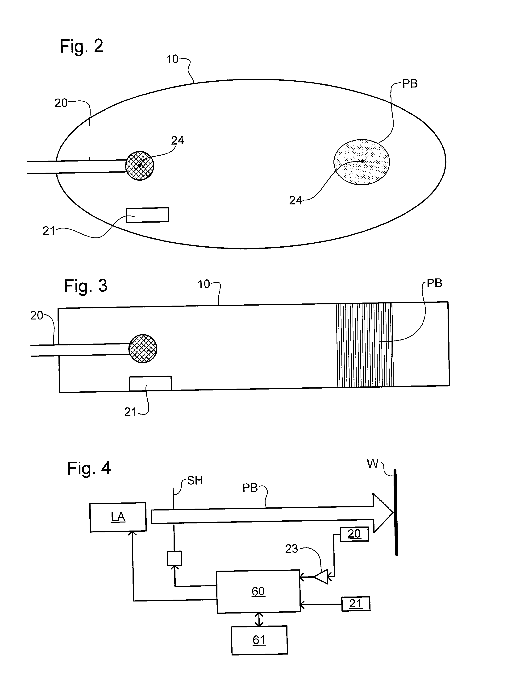
[0058] A second embodiment of the present invention, which may be the same as the first embodiment save as described below, is shown in FIG. 5. The microphone (or micro-barograph) 20 is located in a chamber 50 mounted to the projection system PL below the element 40 directly opposite the wafer W; an element such as element 40 may be referred to hereinafter as the "final" element. The chamber 50 occupies most of the space between the final element 40 and substrate W so that the projection beam intensity as determined from the output of the microphone 20 is as close as possible to the actual dose delivered to the resist. The output signal of the microphone 20 can also be used in combination with the output signal of the energy sensor ES to calibrate, for example, changes of absorption of the projection beam along the path of propagation downstream of the beamsplitter BS as shown in FIG. 1.
embodiment 3
[0059] Embodiment 3
[0060] A third embodiment of the present invention, which may be the same as the first embodiment save as described below, makes use of sound emitted by the substrate when a pulse of radiation of the projection beam is delivered to it. The layout of the acoustic sensor arrangement, shown in FIG. 6, is similar to that of the second embodiment but the microphone 20 is reoriented to pick up sounds emitted by the substrate W. These sounds are caused by the sudden localized heating in the substrate and resist when a pulse of the projection beam PB strikes the substrate W. Local expansion caused by the local heating gives rise to vibrations in the substrate and the emission of sound owing to the large surface area of the substrate. These sounds are picked up by the microphone 20 and their amplitude is indicative of the amount of energy delivered to the substrate in each pulse of radiation.
PUM
 Abstract
Description
Claims
Application Information