Folding rigid-bottomed boat

a rigid-bottomed boat and folding technology, applied in special-purpose vessels, vessel construction, transportation and packaging, etc., can solve the problems of difficulty in carrying both a dinghy and a life-raft or life-boat, and the difficulty of carrying both a dinghy and a life-boa

Inactive Publication Date: 2002-06-27
CALLAHAN STEVEN
View PDF7 Cites 6 Cited by
  • Summary
  • Abstract
  • Description
  • Claims
  • Application Information

AI Technical Summary

Benefits of technology

0014] It is another object of the invention to provide a foldable water craft that may be adapted to t

Problems solved by technology

Although the safety, utility, and comfort of small craft therefore increase with size, increasing size creates problems for storage and transport, especially for auxiliary craft that must be carried aboard other boats, land vehicles, or aircraft.
Many mariners are forced to carry auxiliary craft far smaller than the ideal because of limitations of onboard storage space.
In addition, most mariners need launches (dinghies) for normal commuting between ship and shore, while many of these mariners should also carry conventional life rafts or boats for emergencies at sea, yet available space aboard too often makes the carrying of both a dinghy and life raft or life boat difficult if not impossible.
Inflatable boats with no rigid bottoms provide very limited speed potential in all but very light conditions except under engine power, especially poor performance under sail or oars, and poor directional control in all conditions.
They are also vulnerable to total failure from a puncture or two as well as significant degradation from beaching and other sources of chafe.
Take-apart boats, including rigid boats that disassemble so one part may "nest" in another, or other flexible-skinned craft that are made usable with an internal fr

Method used


Image

  • Folding rigid-bottomed boat
  • Folding rigid-bottomed boat
  • Folding rigid-bottomed boat

Examples


Embodiment Construction

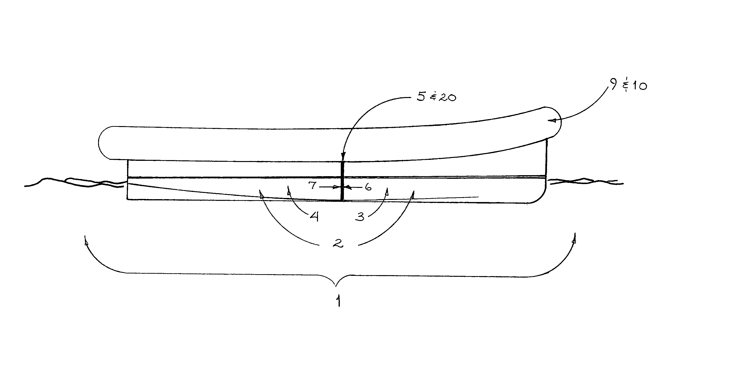
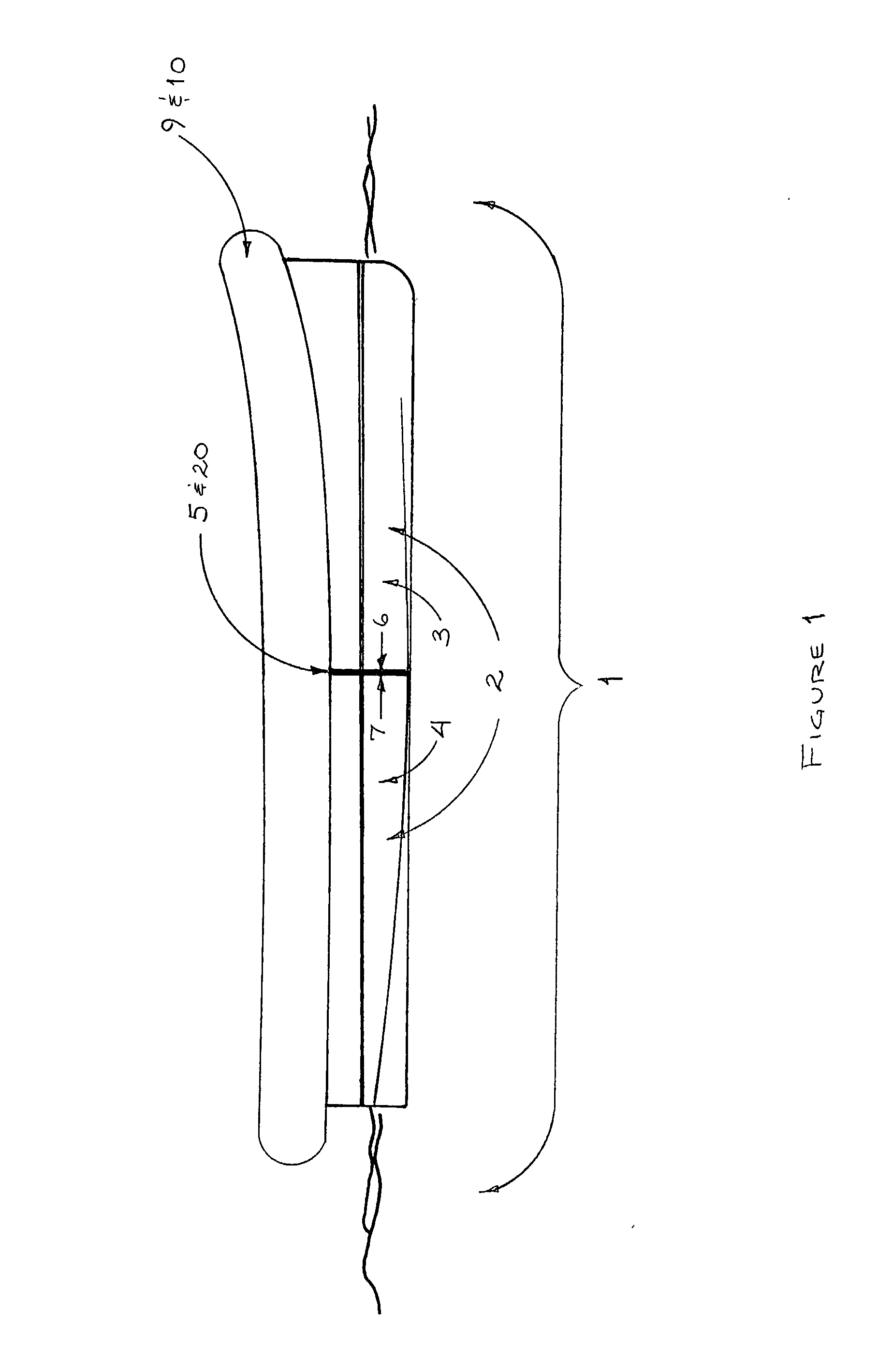
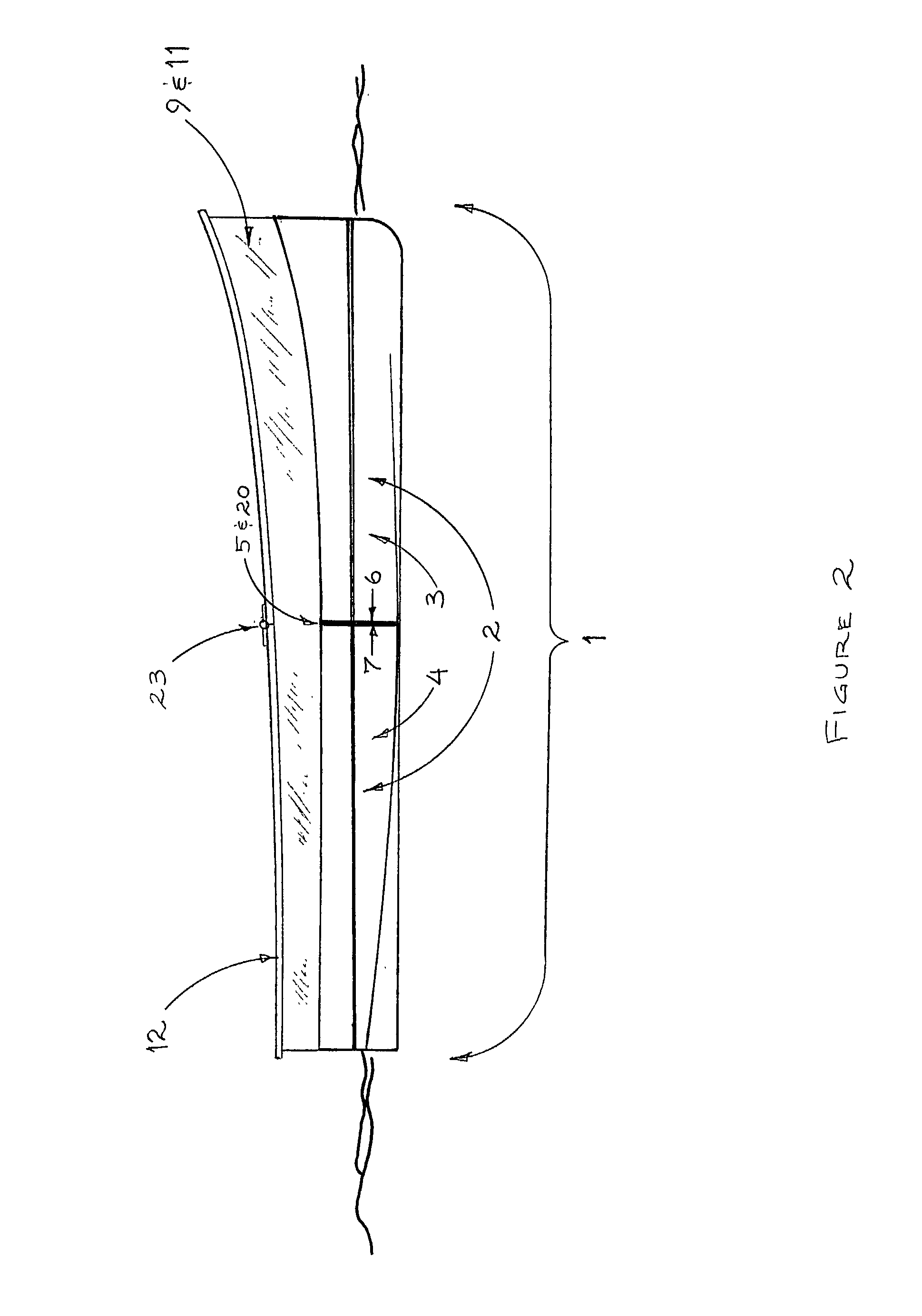
[0041] Referring now specifically to the drawings, the preferred embodiment of the invention is shown in FIGS. 1, 3, 4, 6a, 6b, 8, and 10. As shown in FIG. 3, the unfolded use configuration of the boat 1 is indicated by solid lines and labeled OPEN; the closed configuration for storage and transport is indicated by phantom lines and is labeled CLOSED; rotational lines along which the bow element 3 moves as the boat transitions from the OPEN to CLOSED positions are indicated by a lifted phantom bow and arrowed arcs.

[0042] As shown in FIGS. 1 through 12, the boat 1 features a rigid bottom hull 2--i.e.; one composed of fiberglass reinforced plastic or other composite material (aramid or carbon reinforced laminates included), molded or cast PVC (polyvinylchloride) or similar plastic, wood, metal or other relatively stiff material-in order to enhance the water craft's performance while in use. The hull may be V-bottomed, round-bottomed, step-planed or otherwise shaped to be propelled by ...


PUM

PropertyMeasurementUnit
Lengthaaaaaaaaaa
Volumeaaaaaaaaaa
Flexibilityaaaaaaaaaa

Abstract

A folding rigid boat for routine and emergency use by occupants as an auxiliary watercraft and including complementary rigid bow and rigid stern sections joined together along respective mating edges to form a hull, complementary rigid hinge elements cooperating together to form a centrally-disposed joint pivotally connecting the bow and stern sections along a port-to-starboard axis in vertically spaced-apart relation to the bottom of the hull for permitting the bow and stern sections to be folded onto themselves into a storage configuration and away from each other along the joint into an unfolded use configuration. Flexible topsides are secured to the hull along at least port and starboard sides of the hull for providing an upwardly-extending freeboard to the hull when the boat is in the unfolded use configuration. The topsides are unconnected to and independent of the rigid hinge elements. Waterproofing is carried by the bow and stern sections and is unconnected to and independent of the rigid hinge elements for preventing water leakage through centrally-disposed joint when in the boat is in the unfolded use configuration.

Description

TECHNICAL FIELD AND BACKGROUND OF THE INVENTION[0001] This application is a continuation-in-part of applicant's prior patent application, Ser. No. 09 / 537,337, filed Mar. 29, 2000.[0002] The present invention is the result of the inventor's 30 years of experience with boats, including sailing, designing, and construction, combined with his survival experience in a conventional life raft. Generally, the stability, speed potential, load-carrying capability, and resistance to shipping water from waves and spray increase with a vessel's size. Although the safety, utility, and comfort of small craft therefore increase with size, increasing size creates problems for storage and transport, especially for auxiliary craft that must be carried aboard other boats, land vehicles, or aircraft. Many mariners are forced to carry auxiliary craft far smaller than the ideal because of limitations of onboard storage space. In addition, most mariners need launches (dinghies) for normal commuting between...

Claims


Application Information

Patent Timeline
IPC IPC(8): B63B5/24B63B7/08B63B17/02B63B21/48B63C9/02
CPCB63B5/24B63B7/082B63B17/02B63C9/02B63B2007/003B63B2231/52B63B21/48
Inventor CALLAHAN, STEVEN
Owner CALLAHAN STEVEN
Why Eureka
Try Eureka