Poly(arylene ether) data storage media

a technology of poly(arylene ether) and data storage media, which is applied in the field of poly(arylene ether) data storage media, can solve the problems of difficult pattern creation, pit or groove structure, and inability to store and retrieve data, so as to prevent the sticking of the pae and minimize the effect of decomposition

Inactive Publication Date: 2002-07-18
SABIC INNOVATIVE PLASTICS IP BV
View PDF16 Cites 41 Cited by
  • Summary
  • Abstract
  • Description
  • Claims
  • Application Information

AI Technical Summary

Benefits of technology

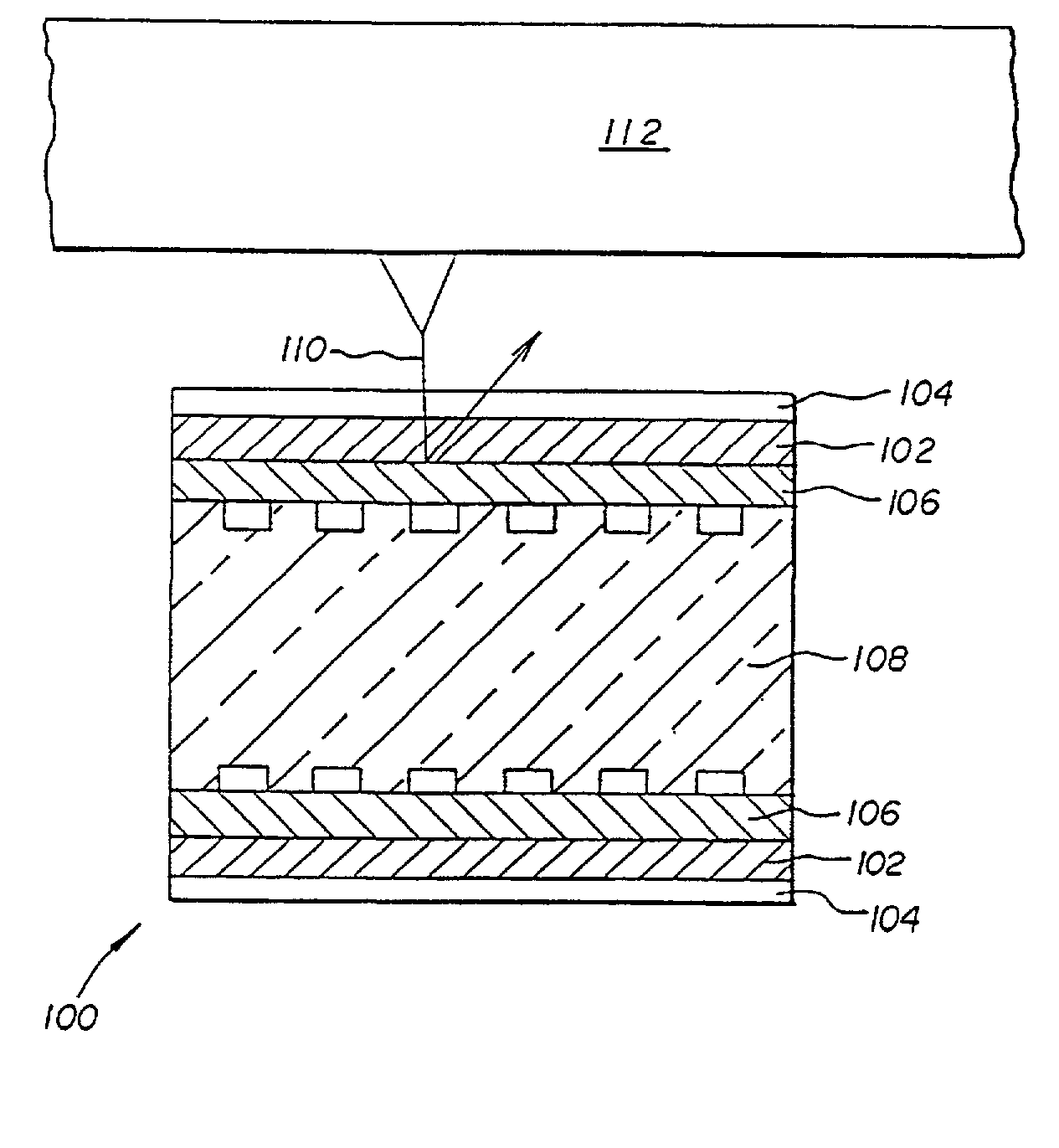
[0016] A storage media can comprise a homogenous or non-homogenous poly(arylene ether) / styrenic material substrate that can be formed in situ with the desired surface features disposed thereon on one or both sides, a data storage layer such as a magneto-optic material also on one or both sides, and an optional protective, dielectric, and / or reflective layers. The substrate can have a substantially homogenous, tapered, concave, or convex geometry, with various types and geometries of reinforcement employed to increase stiffness without adversely effecting surface integrity and smoothness.
[0035] The data storage media using this blend can be produced by first forming the thermoplastic composition using a conventional reaction vessel capable of adequately mixing the various components, such as a single or twin screw extruder, kneader, or the like. The components can either be simultaneously fed through a hopper into the extruder, or the styrenic material(s) can be introduced to the extruder and melted prior to the addition of the PAE to prevent sticking of the PAE. The extruder should be maintained at a sufficiently high temperature to melt the components without causing decomposition thereof. Temperatures of about 270.degree. C. to about 340.degree. C. can be used, with about 280.degree. C. to about 320.degree. C. preferred, and about 290.degree. C. to about 305.degree. C. especially preferred. Similarly, the residence time in the extruder should be controlled to minimize decomposition. Residence times of less than or equal to about 5 minutes (min) or more are typically employed, with less than or equal to about 2 min preferred, and less than or equal to about 1 min especially preferred.

Problems solved by technology

Furthermore, the physical characteristics of the storage media when in use can also affect the ability to store and retrieve data; i.e. the axial displacement of the media, if too great, can inhibit accurate retrieval of data and / or damage the read / write device.
A disadvantage of using such substrates is the difficulty of creating a pattern, e.g., pit or groove structure, on the surface to facilitate tracking of the read / write device or definition of a sector structure.
In the case of magnetic or magneto-optic data storage devices, a patterned structure may also be added in the data layer through magnetic read / write techniques, resulting in decreased area available for data storage.

Method used


Image

  • Poly(arylene ether) data storage media
  • Poly(arylene ether) data storage media
  • Poly(arylene ether) data storage media

Examples


example 2

[0050] Poly(phenylene ether) / polystyrene

[0051] A blend of 60 wt % 0.33 IV poly(phenylene ether) powder (commercially available from GE Plastics) and 40 wt % polystyrene pellets (Nova PSI 72) was extruded in a 40 mm twin screw extruder to make homogeneous, single phase pellets. The resulting pellets were then injection molded to form an optical disk with a grooved surface, with the groove depth of the mold insert ("stamper") being approximately 50 nm deep and a track pitch of approximately 0.8 .mu.. Tg of the material was about 158.degree. C. This material showed superior replication of the grooved structure compared to the blends containing higher poly(phenylene ether) content. The ductility of the material (as measured by Notched Izod, Dynatup, or other impact-type methods) was superior to that of blends containing higher polystyrene content. The disk exhibits improved flatness, lower density, and lower moisture absorption than a typical optical quality polycarbonate disk as in Com...

example 3

[0052] Poly(phenylene ether) / polystyrene

[0053] A blend of 25 wt % 0.33 IV poly(phenylene ether) powder (commercially available from GE Plastics) and 75 wt % polystyrene pellets (Nova PSI 72) was extruded in a 40 mm twin screw extruder to make homogeneous, single phase pellets. The resulting pellets were then injection molded to form an optical disk. Tg of the material was about 124.degree. C. While the flow and replication of this material were superior to that of the higher poly(phenylene ether) content blends, the ductility and Tg are significantly lower. The disk exhibits improved flatness, lower density, and lower moisture absorption than a typical optical quality polycarbonate disk as in Comparative Example 1.

example 4

[0054] Poly(phenylene ether) / poly(phenylene ether) / polystyrene

[0055] A blend of 50 wt % 0.33 IV poly(phenylene ether) powder (commercially available from GE Plastics), 5 wt % 0.12 IV poly(phenylene ether) powder, and 45 wt % polystyrene pellets (Nova PS172) was extruded in a 40 mm twin screw extruder to make homogeneous, single phase pellets. The resulting pellets were then injection molded to form an optical disk with a grooved surface, with the groove depth of the mold insert ("stamper") being approximately 50 nm deep and a track pitch of approximately 0.8 .mu.. Tg of the material was about 155.degree. C. The material showed superior flow compared to a blend which contains 55 wt % 0.33 IV poly(phenylene ether) without any significant sacrifice in ductility. The disk exhibited improved flatness, lower density, and lower moisture absorption than a typical optical quality polycarbonate disk as in Comparative Example 1.


PUM

PropertyMeasurementUnit
glass transition temperatureaaaaaaaaaa
thicknessaaaaaaaaaa
thicknessaaaaaaaaaa

Abstract

A storage media comprises: a substrate comprising at least one plastic resin portion, wherein the plastic resin portion comprises poly(arylene ether) and a styrene material selected from the group consisting of polystyrene, styrenic copolymer(s), and reaction products and combinations comprising at least one of the foregoing styrene material(s), and at least one data layer on the substrate. The data layer can be at least partly read from, written to, or a combination thereof by at least one energy field. Additionally, when the energy field contacts the storage media, the energy field is incident upon the data layer before it could be incident upon the substrate.

Description

[0001] This application is a continuation-in-part application of U.S. patent application Ser. No. 09 / 683,114, Attorney Docket Nos. 08CN08803-25 and GP2-0018-C which is a continuation of and claims the benefit of the filing date of U.S. patent application Ser. No. 09 / 502,968, Attorney Docket Nos. 08CN08803 and GP2-0018 which claims the benefit of the filing date of U.S. Provisional Application Serial No. 60 / 120,101 filed Feb. 12, 1999, Attorney Docket Nos. GP2-0001 and 8CN-8803PA; No. 60 / 134,585 filed May 17, 1999, Attorney Docket No. 8CN-8807PA; No. 60 / 137,883 filed Jun. 7, 1999, Attorney Docket No. 8CU-5845PA; No. 60 / 137,884 filed Jun. 7, 1999, Attorney Docket No. 8CU-5846PA; and No. 60 / 146,248 filed Jul. 29, 1999, Attorney Docket Nos. 8CN-8826PA and GP2-0018; the entire contents of each application are hereby incorporated by reference.BACKGROUND OF INVENTION[0002] Optical, magnetic and magneto-optic media are primary sources of high performance storage technology that enable high ...

Claims


Application Information

Patent Timeline
Patent Type & Authority Applications(United States)
IPC IPC(8): G11B5/82G11B5/73G11B7/246G11B7/257G11B7/258G11B11/105G11C13/02
CPCB82Y10/00G11B5/73G11B5/743G11B5/82G11B7/24038G11B7/2433G11B7/246G11B7/2472G11B7/248G11B7/252G11B7/2533G11B7/2534G11B7/2536G11B7/2542G11B7/2548G11B7/2578G11B7/258G11B11/10586G11B2007/25708G11B2007/2571G11B2007/25711G11B2007/25713G11B2007/25715G11B5/73937
Inventor FEIST, THOMAS PAULDAI, KEVIN HSINGTAOMERFELD, GLEN DAVID
Owner SABIC INNOVATIVE PLASTICS IP BV
Why Eureka
Try Eureka