Fuel injection pump

a technology of fuel injection pump and piston, which is applied in the direction of liquid fuel feeder, machine/engine, electric control, etc., can solve the problems of insufficient stop and the position of the injection adjuster piston

Inactive Publication Date: 2002-08-08
ROBERT BOSCH GMBH
View PDF0 Cites 0 Cited by
  • Summary
  • Abstract
  • Description
  • Claims
  • Application Information

AI Technical Summary

Benefits of technology

[0006] The fuel injection pump of the invention, having the characteristics of claim 1, offers the advantage that the starting spring acting counter to the restoring spring keeps the piston of the injection adjuster in the optimal position for starting the engine when the fuel injection pump is at a stop and consequently no fluid flow with which the piston could be acted upon is available. This optimal position, which is selected especially with a view to starting performance at low temperatures, can preferably be determined by adaptation of the prestressing and the spring constants of the restoring spring and the starting spring.[0007] In a preferred embodiment, it is provided that the starting spring is disposed in the interior of the piston. This produces an especially compact structural shape.[0008] In one embodiment, it is provided that the starting spring is braced by one end on the housing of the injection pump. In this way, a simple, open construction at little additional cost is obtained.[0009] In an alternative embodiment, it is provided that the starting spring is braced by one end on an auxiliary piston, which is supported displaceably in a receiving bore in the piston and is braced on the housing. In this encapsulated version, only a relatively short spring is needed, and such a spring can be designed well.[0010] To prevent the auxiliary piston from coming loose from the injection adjuster piston, a securing ring that limits the displaceability of the auxiliary piston can be disposed in the receiving bore.[0011] The invention is described below in terms of two preferred versions, which are shown in the accompanying drawings. Shown are:[0012] FIG. 1, a fuel injection pump in a sectional view;[0013] FIG. 2, an injection adjuster of a fuel injection pump of the invention, in a schematic sectional view;[0014] FIG. 3, a detail of the piston of the injection adjuster in a first version, in a sectional view; and[0015] FIG. 4, a detail of the piston of the injection adjuster in a second version, in a sectional view.

Problems solved by technology

As a consequence, however, when the fuel injection pump is at a stop, the piston of the injection adjuster is in the "late" position, since at a stop no fluid flow can be furnished, and thus only the force that is furnished by the restoring spring acts on the piston.
A disadvantage of this is that the position of the injection adjuster piston, which is predetermined by the restoring spring, at a stop is not optimal for starting an internal combustion engine supplied by the fuel injection pump.

Method used


Image

  • Fuel injection pump
  • Fuel injection pump
  • Fuel injection pump

Examples


Embodiment Construction

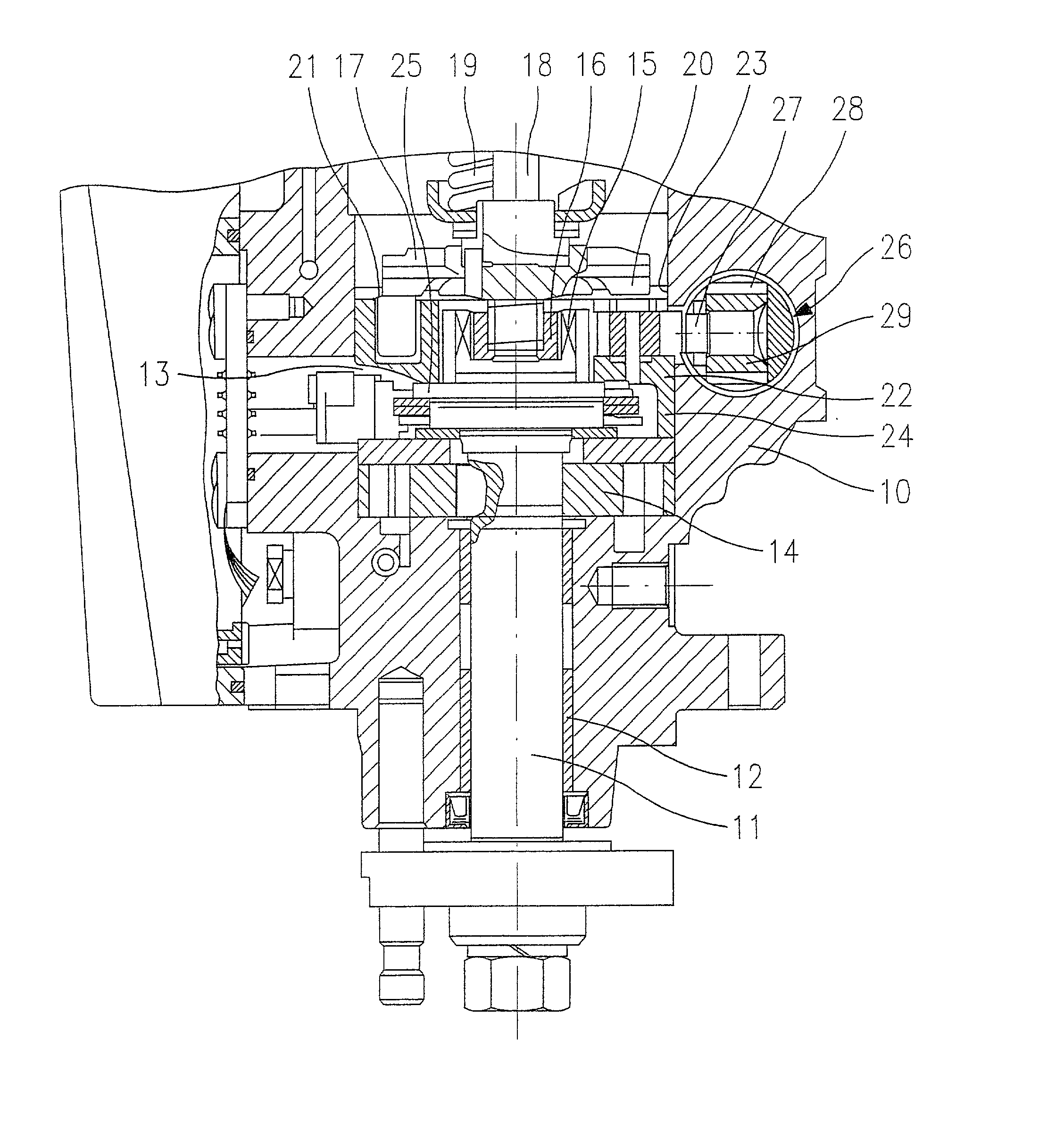
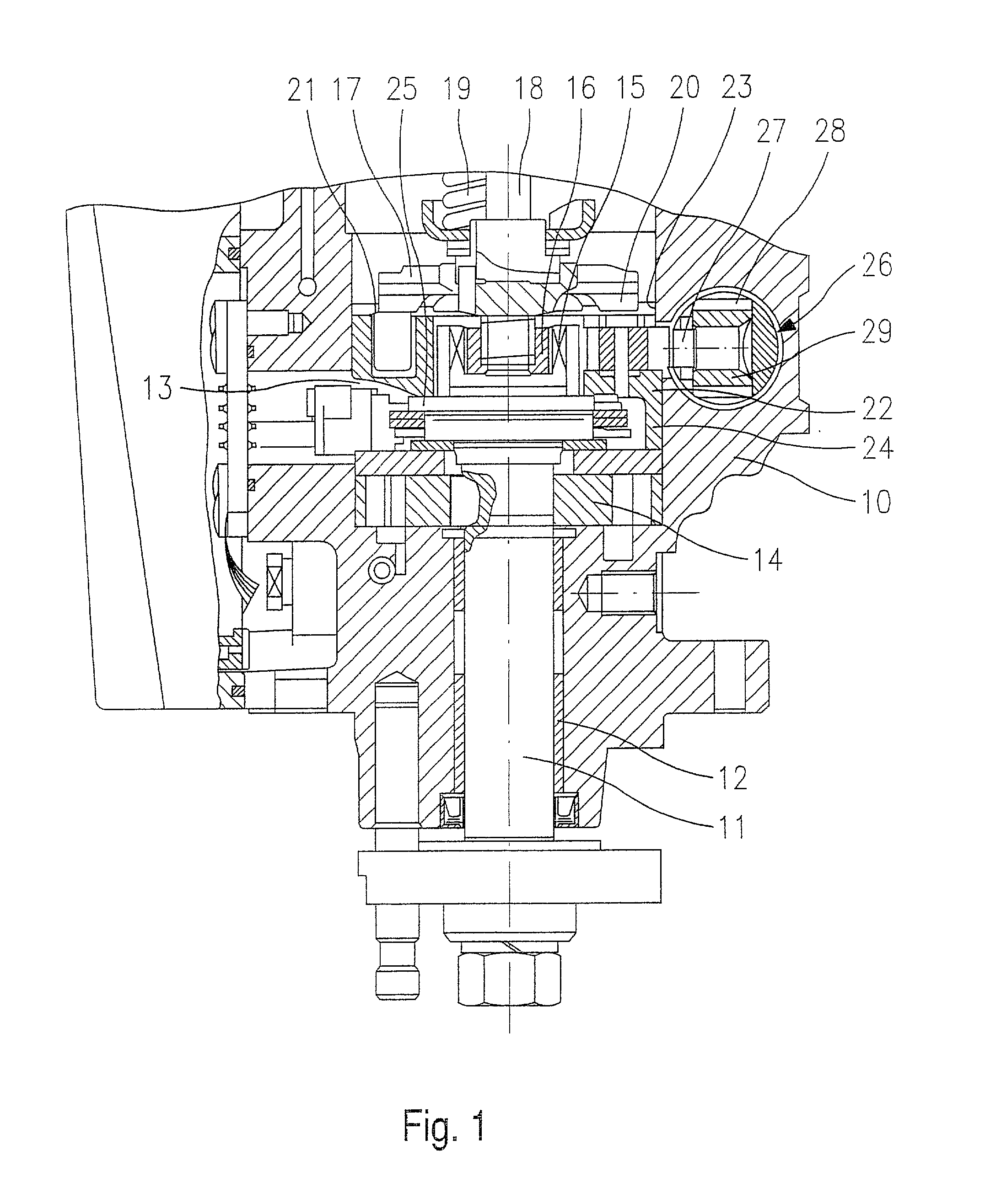
[0016] The fuel injection pump, shown in part in axial longitudinal section in FIG. 1, has a housing 10 in which a drive shaft 11 is rotatably supported with slide bearings 12. The housing 10 surrounds a pump interior 13, which is filled with fuel that is under pressure. The filling of the pump interior 13 is attained with the aid of a prefeed pump 14, which is disposed in the pump interior 13 and is driven by the drive shaft 11.

[0017] On the face end of the drive shaft 11 is a pair of claws 15, which via a slaving piece 16 and suitable claws, not shown, drives an end cam plate 17 to rotate. A pump piston 18 is coupled in a manner fixed against relative rotation to the end cam plate 17 and is pressed against the end cam plate 17 by a spring 19 and presses a cam race 20, disposed on the end cam plate 17, against rollers 21, which are supported in a radial orientation in a roller ring 22. The roller ring is supported rotatably by its circular outer contour in a corresponding circular-...


PUM


Abstract

In a fuel injection pump with a housing (10), a metering pump (18, 20) and an injection adjuster (26) for the metering pump, in which the injection adjuster has a piston (28) that is acted upon by a restoring spring (48), the starting performance of the internal combustion engine supplied by the injection pump is to be improved. To that end, a starting spring (50) is provided in addition, which acts on the piston (28) and acts counter to the restoring spring.

Description

PRIOR ART[0001] The invention relates to a fuel injection pump, having a metering pump and an injection adjuster for the metering pump, in which the injection adjuster has a piston that is acted upon by a restoring spring.[0002] One such fuel injection pump is known from German Patent Disclosure DE 43 44 865 A1. This fuel injection pump is a so-called distributor injection pump, in which a single pump piston of the metering pump is used to inject the correct fuel quantity into the appropriate cylinder of an internal combustion engine. During the revolution of the drive shaft, the pump piston executes as many strokes as there are engine cylinders to be supplied; the drive shaft of the fuel injection pump rotates at half the rotary speed of the engine crankshaft.[0003] Since the fuel need not always be injected into the applicable cylinders at the same instant, with reference to the angle of rotation of the crankshaft, the injection adjuster is provided, by means of which the instant ...

Claims


Application Information

Patent Timeline
IPC IPC(8): F02D1/04F02D1/18F02M41/12
CPCF02D2001/186F02M41/128
Inventor FEHLMANN, WOLFGANGGEIGER, WOLFGANGJONAS, STEPHAN
Owner ROBERT BOSCH GMBH
Why Eureka
Try Eureka