Light diffusion sheet and backlight unit using the same

a backlight unit and light diffusion technology, applied in lighting and heating apparatus, instruments, mechanical equipment, etc., can solve the problems of restricted deflection of light diffusion sheets when lamps are lit, and achieve the effects of increasing the cross-linking density of the binder, and reducing the number of scratches

Inactive Publication Date: 2002-08-22
KEIWA INCORPORATED
View PDF0 Cites 48 Cited by
  • Summary
  • Abstract
  • Description
  • Claims
  • Application Information

AI Technical Summary

Benefits of technology

[0063] According to the invention, even when a plurality of light diffusion sheets are stacked together on top of one another during manufacture, delivery, storage and other occasions, possible occurrence of scratch defects in the rear faces of the sheets can be prevented and handling of the sheets becomes easy, so that the attachment of the sheets to a backlight unit can be facilitated.[0064] In the light diffusion sheet of the invention, possible occurrence of scratch defects in the sticking-inhibiting layer is prevented, so that degradation of optical properties such as interference of light beam transmission caused by scratches in the sticking-inhibiting layer can be avoided, thereby maintaining the desired optical properties.[0065] In addition, by use of a wax for the light diffusion sheet of the invention, light beams passing through the light diffusion layer can be uniformly diffused utilizing optical refraction and reflection at the interface of the wax. Since the wax dispersed in the binder prevents occurrence of scratches in the light diffusion sheet, damage which is possibly caused in the contact surfaces of a plurality of light diffusion sheets when stacked together on top of one another can be avoided.[0066] Further, the apparent crystallinity of the light diffusion sheet of the invention is increased by dispersing the micro inorganic filler in the light diffusion sheet, whereby the heat resistance of the light diffusion sheet can be increased to restrict the deflection of the sheet caused by heat generation when the lamp is lit.

Problems solved by technology

Consequently, the deflection of the light diffusion sheet when the lamp is lit can be restricted.

Method used


Image

  • Light diffusion sheet and backlight unit using the same
  • Light diffusion sheet and backlight unit using the same
  • Light diffusion sheet and backlight unit using the same

Examples


Embodiment Construction

[0022] With reference to the accompanying drawings, embodiments of the invention will be hereinafter described in detail.

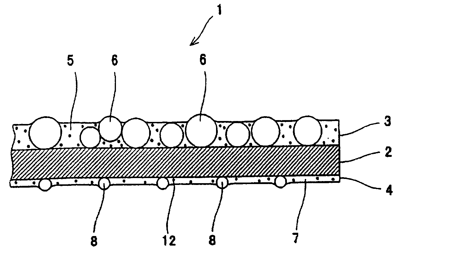
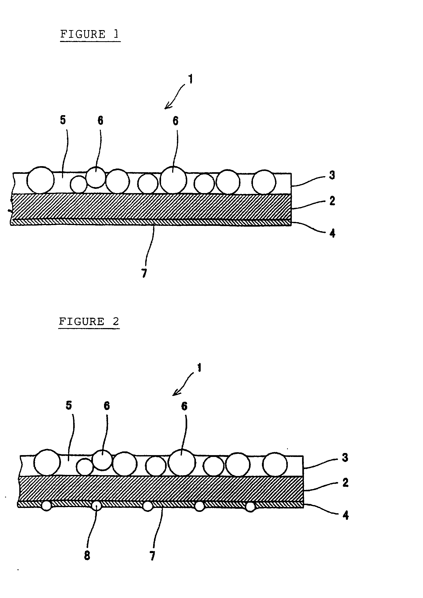
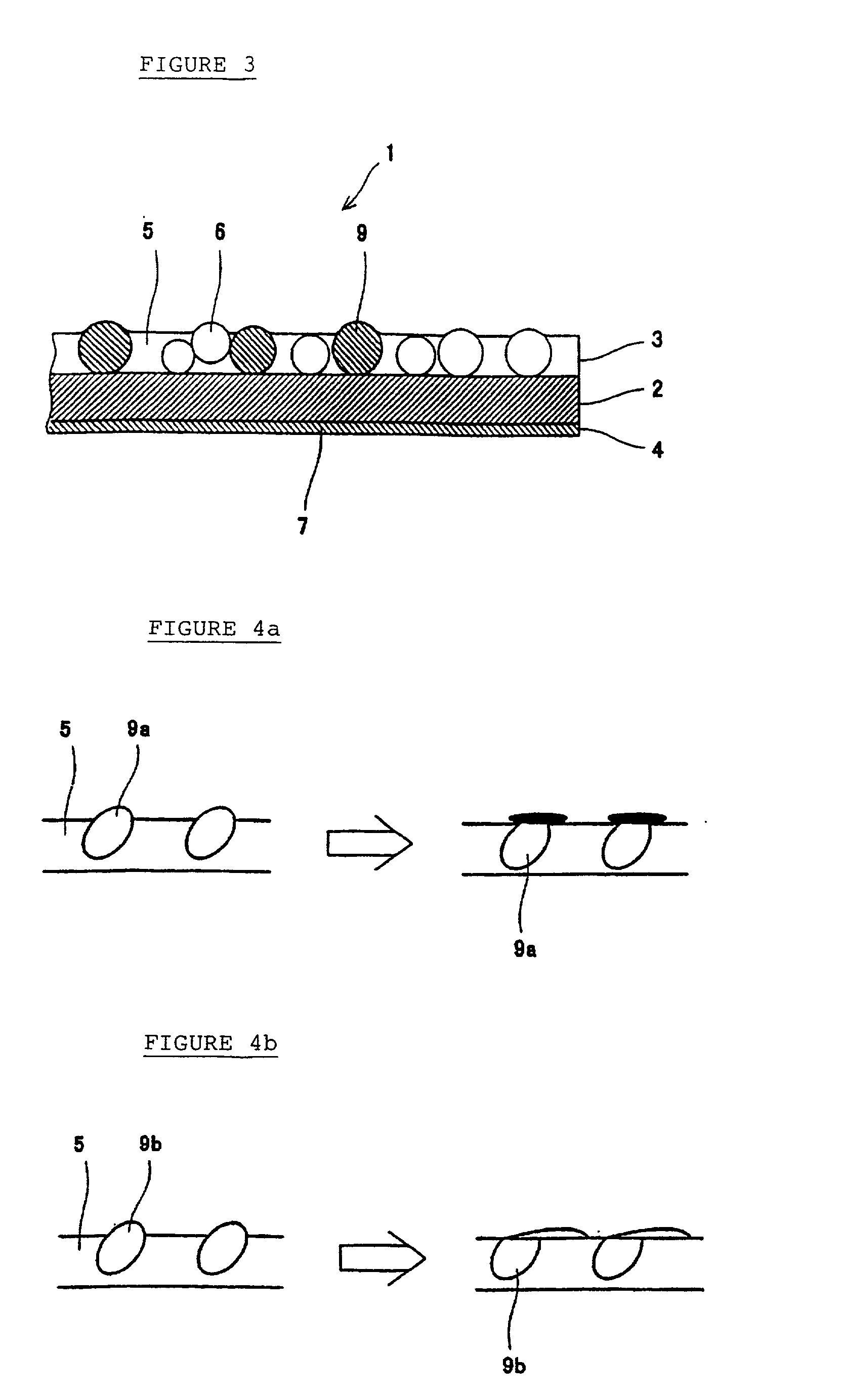
[0023] Referring to FIG. 1, a light diffusion sheet 1 of the invention is generally comprised of a base sheet 2, a light diffusion layer 3 laminated on the front face of the base sheet 2, and a flat sticking-inhibiting layer 4 laminated on the rear face of the base sheet 2.

[0024] The base sheet 2 needs to be permeable to light beams (ray) and is therefore formed from a transparent synthetic resin, particularly, colorless transparent synthetic resin. The synthetic resin used for the base sheet 2 is not particularly limited, but such resin may include polyethylene terephthalate, polyethylene naphthalate, acrylic resin, polycarbonate, polystyrene, polyolefin, cellulose acetate and weather-resistant vinyl chloride. The thickness of the base sheet 2 is not particularly limited, but may be within the range of from about 10 .mu.m to about 500 .mu.m and more preferably wi...


PUM

PropertyMeasurementUnit
Tgaaaaaaaaaa
Tgaaaaaaaaaa
particle sizeaaaaaaaaaa

Abstract

A light diffusion sheet comprising a transparent base material sheet; a light diffusion layer laminated on a surface of the base material sheet and containing beads dispersed within a binder; and a sticking-inhibiting layer laminated on a rear face of the base material sheet, wherein the binder of the light diffusion layer contains a thermosetting resin and the sticking-inhibiting layer is a resin layer containing an ionizing radiation curable resin. In the light diffusion sheet of the invention, which employs an ionizing radiation curable resin for the binder of the sticking-inhibiting layer, the cross-linking density of the binder can be increased, whereby the wear resistance of the sticking-inhibiting layer as well as the wear resistance of the rear face of the light diffusion sheet can be increased. Further, possible occurrence of scratches in the sticking-inhibiting layer, which is attributable to the contact between the sticking-inhibiting layer and the beads of the light diffusion layer, can be effectively avoided.

Description

[0001] The present invention relates to a light diffusion sheet for use in a backlight unit incorporated in a liquid crystal display (LCD) and to a backlight unit using a light diffusion sheet.[0002] In the field of LCDs, backlight systems have been widely utilized for illuminating a liquid crystal layer from its back for light emission. A known LCD has a backlight unit placed on the underside of a liquid crystal layer. Such a backlight unit 20 is generally comprised of, as shown in FIG. 8, a bar-like lamp 21 (light source); a light guide plate 22, in the form of a square plate, placed with one end extending along the lamp 21; a light diffusion sheet 23 placed on the surface of the plate 22; and a prism sheet 24 placed on the surface of the sheet 23.[0003] In the backlight unit 20, light beams (ray) emitted from the lamp 21 and incident on the plate 22 are reflected off the side faces of the plate 22 and reflective dots or a reflective sheet (not shown) on the rear face of the plate...

Claims


Application Information

Patent Timeline
Patent Type & Authority Applications(United States)
IPC IPC(8): G02B5/02F21V3/04F21V8/00G02B6/00G02F1/1335G02F1/13357
CPCF21V3/04G02B6/0051G02B6/0065G02F1/1335
Inventor HARADA, KENICHIMASAKI, HITOSHI
Owner KEIWA INCORPORATED
Why Eureka
Try Eureka