
Plastic object

a technology of plastic objects and objects, applied in the field of plastic objects, can solve the problems material deterioration, and unsuitability for use, and achieve the effects of low thermal conductivity of polymeric materials

Inactive Publication Date: 2002-08-29
NITTO DENKO CORP
View PDF1 Cites 31 Cited by
  • Summary
  • Abstract
  • Description
  • Claims
  • Application Information

AI Technical Summary

Problems solved by technology

Of such methods (techniques), the techniques in which heat, pressure, or the like is applied are mostly used for modifying a plastic object by applying heat or pressure to the whole plastic object, and are unsuitable for use in such a manner that heat or pressure is applied only to a desired position (portion) in a plastic object to form a part having a structure different from that of the other inner parts of the plastic object.
In contrast, in the case of polymeric materials, it is necessary to avoid high energy irradiation because irradiation at a high energy may result in material deterioration.
However, polymeric materials are characterized by low thermal conductivity.
Due to the low thermal conductivity, polymeric materials tend to heat up.
However, the formation of an induced structure in plastic objects as polymeric materials by irradiation with a laser light having an ultrashort pulse duration of 10.sup.-12 second or shorter (e.g., on the order of femtosecond) has not been investigated enthusiastically as compared with that in inorganic glass materials.
If a plastic object containing structurally modified parts the distance between which is smaller than 5 .mu.m is to be produced, there are cases where the structurally modified parts are fused to one another during the formation thereof, making it impossible to give independent structurally modified parts.
For example, in the case where the structurally modified part is one formed by the aforementioned structural modification caused by thermal fusion and cooling, the structurally modified part tends to have insufficient stability because it is apt to suffer a structural change due to its relaxation behavior.
However, in the case where a component coagulates or segregates during cooling after melting to cause phase separation, the resulting structurally modified part has factors therein which make the part unstable, according to the state during the cooling after melting (e.g., cooling temperature and cooling rate).
If the amorphous plastic object has a glass transition temperature lower than ordinary temperature, the structure formed is unstable because it changes with time.
Consequently, it is undesirable to use a colored plastic object or a plastic object containing scattering particles in a large amount which considerably absorb or scatter light in the visible wavelength region.
It should be noted that this irradiation may result in cracks.
In addition, the irradiation energy for the ultrashort-pulse-duration laser light may be low.

Method used


Image

  • Plastic object
  • Plastic object
  • Plastic object

Examples


example 2

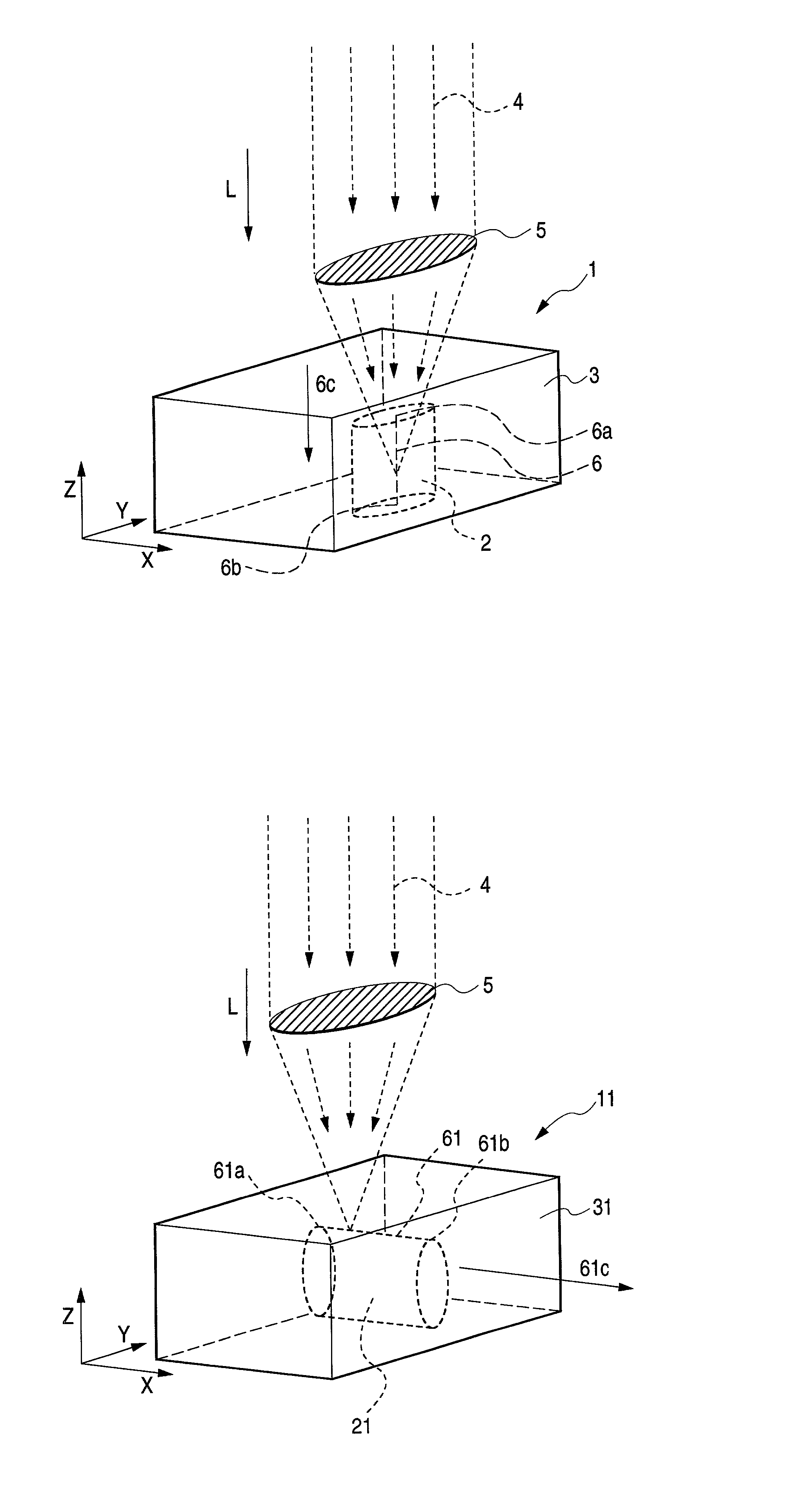
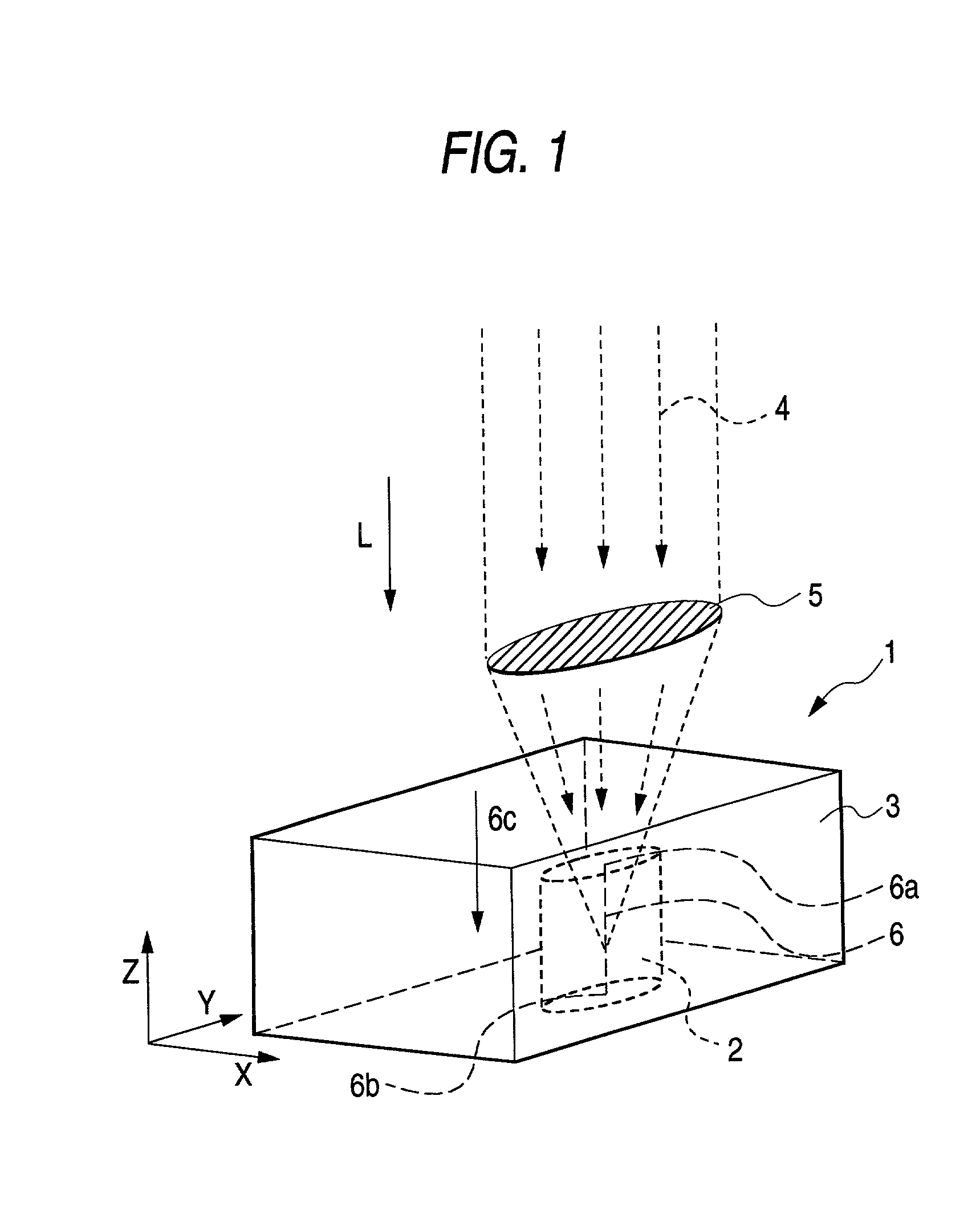
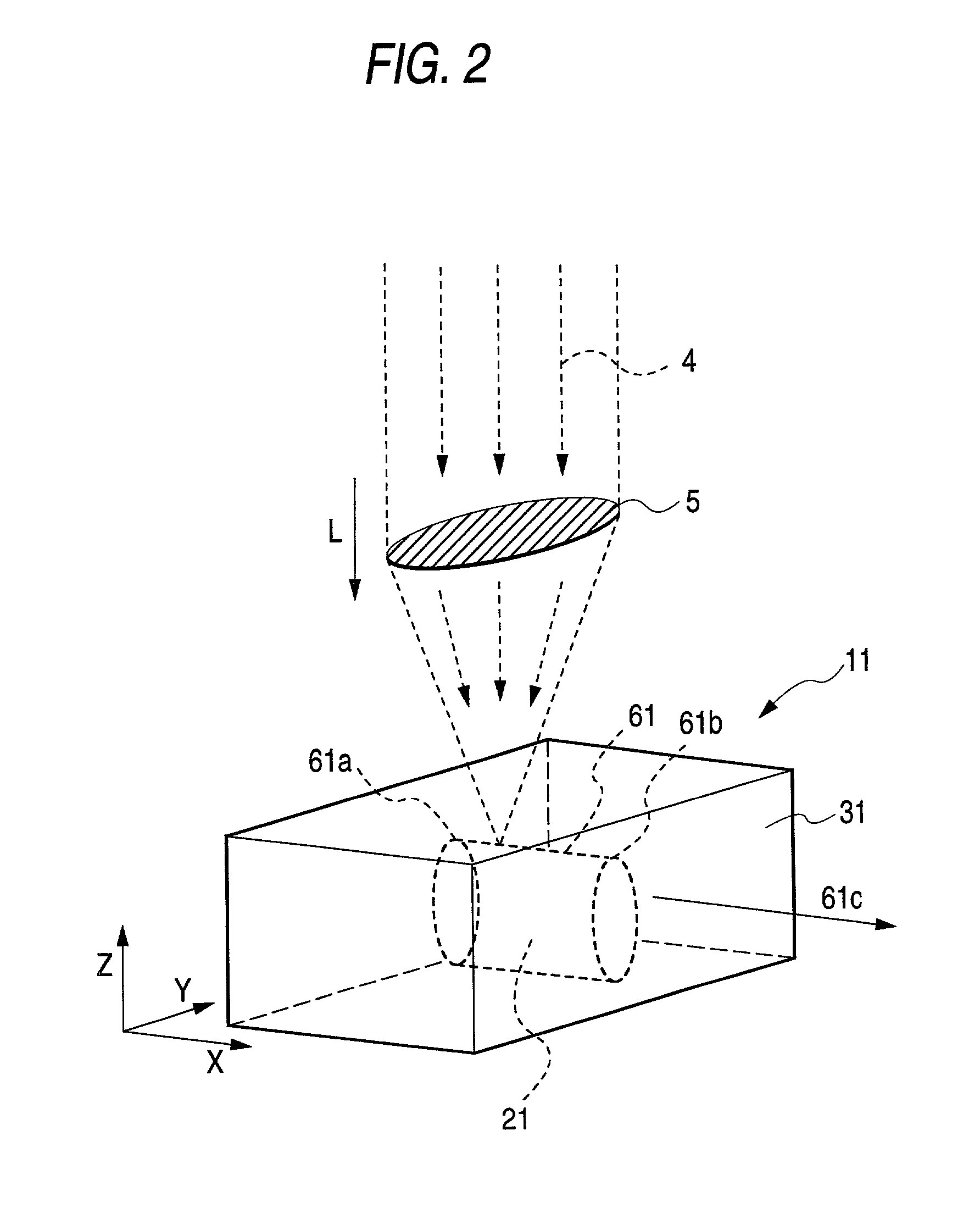
[0073] Irradiation with an ultrashort-pulse-duration laser light was conducted in the same manner as in Example 1, except that an objective lens having a magnifying power of 20 diameters was used. As a result, a structurally modified part having a structure different from that of the original sample A was formed in the sample A. This structurally modified part extended from the focus position where irradiation with the ultrashort-pulse-duration laser light had been initiated (irradiation initiation position) to the focus position where the irradiation had been terminated (irradiation termination position). Thus, a plastic object having the structurally modified part was obtained. In this structurally modified part, a section thereof obtained by cutting along a plane perpendicular to the focus position traveling direction had a nearly elliptic shape (approximately elliptic shape). The nearly elliptic shape had a minor-axis length of about 5 .mu.m and a major-axis length of about 40 ....

example 3

[0074] Irradiation with an ultrashort-pulse-duration laser light was conducted in the same manner as in Example 1, except that the following sample B (a rectangular parallelopiped having a thickness of 0.5 mm) was used as the sample to be irradiated. As a result, a structurally modified part having a structure different from that of the original sample B was formed in the sample B. This structurally modified part extended from the focus position where irradiation with the ultrashort-pulse-duration laser light had been initiated (irradiation initiation position) to the focus position where the irradiation had been terminated (irradiation termination position). Thus, a plastic object having the structurally modified part was obtained. In this structurally modified part, a section thereof obtained by cutting along a plane perpendicular to the focus position traveling direction had a nearly rectangular shape (approximately rectangular shape). The nearly rectangular shape had a minor axi...


PUM

PropertyMeasurementUnit
length LLaaaaaaaaaa
length LLaaaaaaaaaa
distanceaaaaaaaaaa

Abstract

A plastic object having a part whose structure has been modified by irradiation with a laser light having an ultrashort pulse duration of 10-12 second or shorter. The plastic object has a structurally modified part whose structure has been modified by irradiation with a laser light having a pulse duration of 10-12 second or shorter. The laser light having a pulse duration of 10-12 second or shorter may have an irradiation energy of 500 mW or lower. The plastic object may have the structurally modified part in an inner portion thereof. The structurally modified part preferably extends in a direction parallel or perpendicular to the direction of the laser light irradiation.

Description

[0001] The present invention relates to a plastic object. More particularly, the invention relates to a highly functional, high-performance plastic object which has a structurally modified part in any desired inner portion thereof.DESCRIPTION OF THE RELATED ART[0002] Recently, there is a growing desire for the impartation of higher functions to surfaces or inner portions of plastic objects (parts). Investigations for satisfying the desire are being made from two angles, i.e., investigations on techniques concerning materials for producing a plastic object which itself is made of a polymer alloy or composite and investigations on techniques concerning processing in which functional portions are incorporated or structural control is conducted according to desired functions. Examples of higher functions or higher performances desired to be imparted to inner portions (bulk) of plastic objects include electrical or optical conductivity, light transmitting or shielding properties, permeab...

Claims


Application Information

Patent Timeline
Patent Type & Authority Applications(United States)
IPC IPC(8): B29C35/08B29C71/04G02B5/02C08J7/00C08J7/18G02B6/13
CPCB29C71/04B29C2035/0838C08J7/18
Inventor KATAYAMA, SHIGERUHORIIKE, MIKA
Owner NITTO DENKO CORP
Learn More