Starting control method of and control apparatus for synchronous motor, and air conditioner, refrigerator, washing machine and vacuum cleaner each provided with the control apparatus

a technology of synchronous motors and control apparatuses, which is applied in the direction of electronic commutators, motor/generator/converter stoppers, dynamo-electric converter control, etc., can solve the problem of increasing the current of the motor too significantly, not being able to detect the magnetic pole position of the rotor with the corresponding method, and not being able to start the motor

Inactive Publication Date: 2002-08-29
HITACHI LTD
View PDF0 Cites 59 Cited by
  • Summary
  • Abstract
  • Description
  • Claims
  • Application Information

AI Technical Summary

Problems solved by technology

However, since the counter-electromotive force mentioned above is induced into the stator coils by the rotation of the rotor, when the motor is in a stopped status, the magnetic pole position of the rotor cannot be detected with the corresponding method.
Therefore, when the starting current conversion time interval is too short and the starting voltage to be applied is too low, although the motor can be started if the load torque is small enough, it may not be possible for the motor to be started if the load torque is too large, since the motor may be insufficient in output torque.
Conversely, when the starting current conversion time interval is long enough and the starting voltage to be applied is high enough, although the motor can be started even if the load torque is too large, in the event that the load torque is too small, this will increase the motor current too significantly, thus easily generating an eddy current and, in the worst case, damaging the inverter module and the motor.
In short, under the low-frequency starting method based on prior art, since current conversion independent of the rotor position occurs during synchronous operation, the motor is difficult to start properly, if the load torque is unknown.
In addition, in the case of the prior art, since current conversion independent of the rotor position occurs during synchronous operation, if the starting load changes significantly, the relationship between the position of the rotor and the cycle time of the load changes may not enable the motor to be started.
Furthermore, during synchronous operation, since current conversion independent of the rotor position occurs, the possible significant changes in the output torque of the motor may cause significant vibration of the frame in which the motor is enclosed.
Under the prior art, since current conversion independent of the rotor position occurs during synchronous operation, the motor characteristics cannot be utilized sufficiently and the motor is difficult to apply to products in which the motor speed needs to be increased rapidly.

Method used


Image

  • Starting control method of and control apparatus for synchronous motor, and air conditioner, refrigerator, washing machine and vacuum cleaner each provided with the control apparatus
  • Starting control method of and control apparatus for synchronous motor, and air conditioner, refrigerator, washing machine and vacuum cleaner each provided with the control apparatus
  • Starting control method of and control apparatus for synchronous motor, and air conditioner, refrigerator, washing machine and vacuum cleaner each provided with the control apparatus

Examples


Embodiment Construction

[0037] Embodiments of the brushless DC motor control apparatus pertaining to the present invention, and of electrical appliances using brushless DC motors driven by the corresponding control apparatus, are described below, referring to FIGS. 1 to 11.

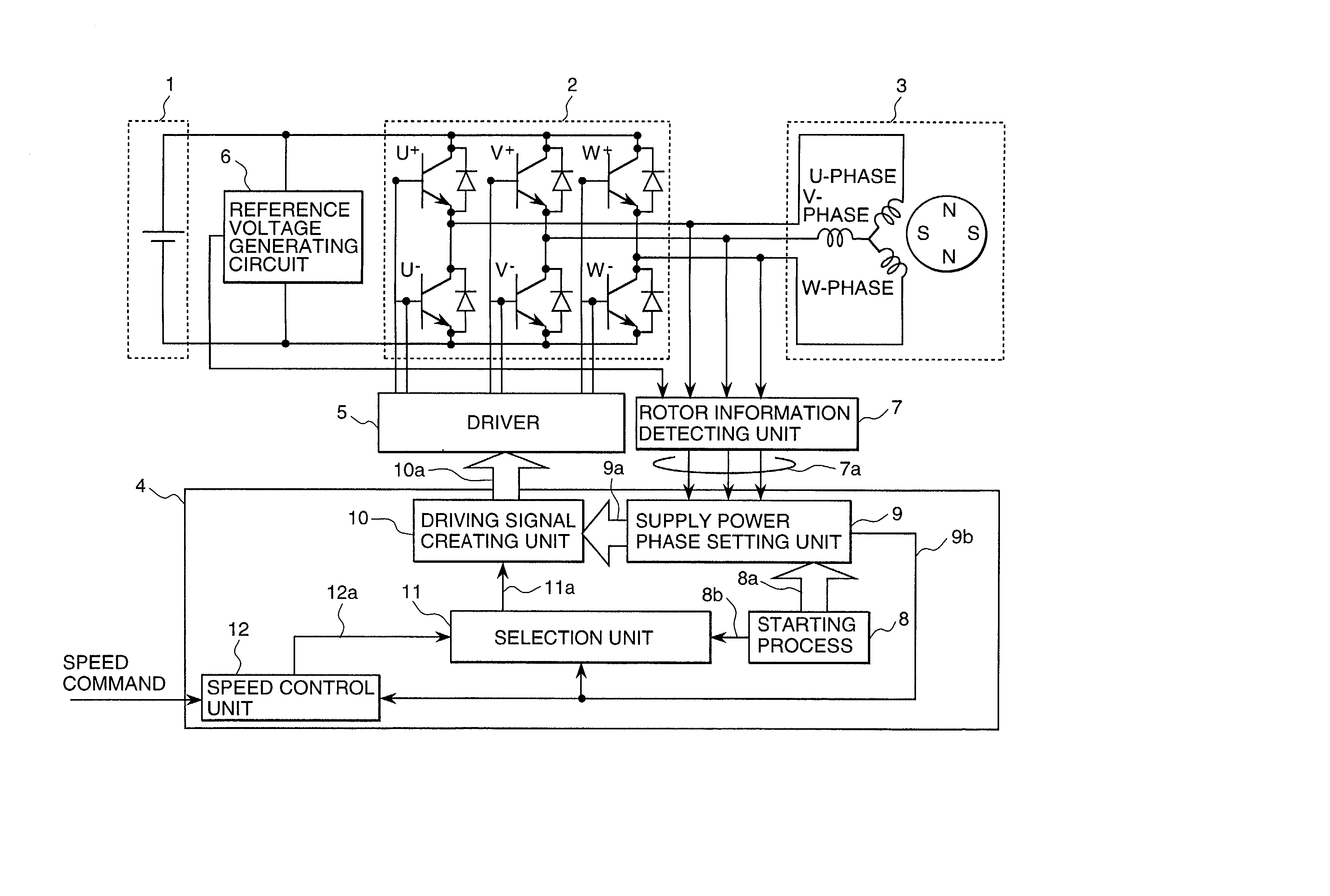
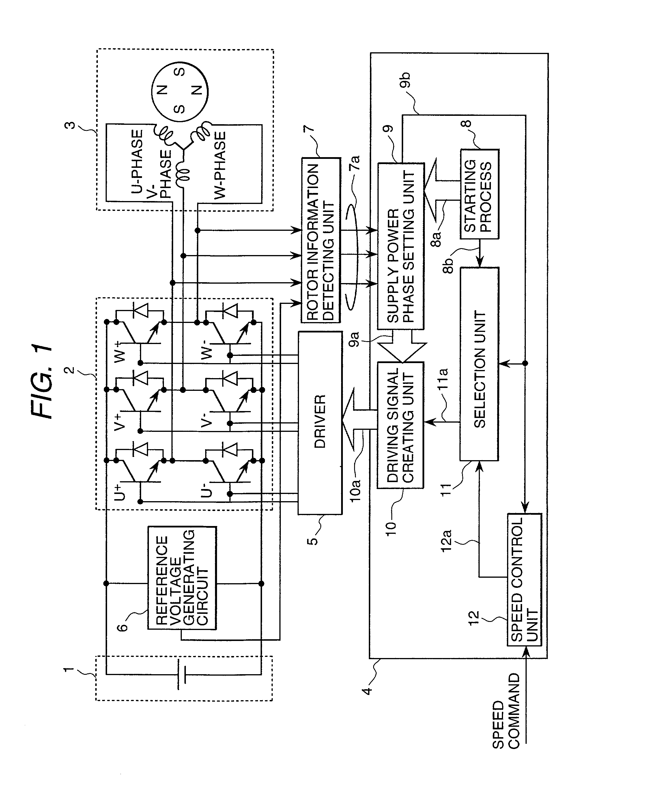
[0038] FIG. 1 is a block diagram showing an embodiment of the brushless DC motor control apparatus pertaining to the present invention. This brushless DC motor control apparatus has an inverter circuit 2 which rotates a synchronous motor 3 by converting the voltage of a DC power supply 1 into an AC voltage of any pulse width and supplying the AC voltage to the stator coils of the above-mentioned synchronous motor 3, a control circuit (one-chip microcomputer or hybrid IC) 4 which controls synchronous motor 3 according to speed command signal, a driver 5 which drives the aforementioned inverter circuit 2 in accordance with the above-mentioned control circuit 4, and a rotor information detection unit 7 which compares the terminal voltage of...


PUM


Abstract

After the rotor position has been fixed prior to the start of a motor, the driving mode can be rapidly switched to sensorless driving and the motor can be started and controlled, by conducting current conversions in such a power supply pattern that increases the starting output torque of the motor, and controlling the inverter output voltage.

Description

[0001] 1. Field of the Invention[0002] The present invention relates to a controller that controls the rotational speed of a synchronous motor to the desired speed, an air conditioner that provides room air conditioning by controlling its internal compressor / blower driving synchronous motor by use of the above-mentioned controller, a refrigerator that provides refrigeration by controlling its internal compressor / blower driving synchronous motor by use of the controller, a washing machine that washes clothes by controlling its pulsator / spin-dry tub driving synchronous motor by use of the controller, and a vacuum cleaner that cleans rooms by controlling its blower driving synchronous motor by use of the controller.[0003] 2. Description of Prior Art[0004] Because of their ease in maintenance, brushless direct-current (DC) motors each having a permanent magnet rotor and a stator coil assembly, are used in air conditioners, refrigerators, washing machines, and the like. Brushless DC moto...

Claims


Application Information

Patent Timeline
Patent Type & Authority Applications(United States)
IPC IPC(8): A47L9/28D06F33/02H02K19/10H02P1/46H02P1/52H02P6/06H02P6/08H02P6/17H02P6/20H02P6/21H02P21/34H02P23/16H02P25/026H02P27/06
CPCH02P1/46H02K19/10
Inventor KAWABATA, YUKIOENDO, TSUNEHIROISHII, MAKOTOTAKAKURA, YUHACHIINOUE, TORU
Owner HITACHI LTD
Why Eureka
Try Eureka