WDM optical network and switching node with pilot tone communications

a technology of optical network and switching node, which is applied in the direction of multiplex communication, transmission monitoring, electromagnetic repeaters, etc., can solve the problems of slow and costly process of upgrading the capacity of the ring, the entire network may have to be upgraded, and the new payload cannot be transported. , to achieve the effect of low overall loss and minimal loss

Inactive Publication Date: 2002-09-12
CIENA
View PDF0 Cites 31 Cited by
  • Summary
  • Abstract
  • Description
  • Claims
  • Application Information

AI Technical Summary

Benefits of technology

0017] An important advantage of the present invention is that each wavelength essentially provides a protocol independent high speed bit pipe between a pair of nodes with minimal loss.
0018] A node in one embodiment may also include a cross connect switch for changing wavelengths. For example, if a path is established between node A and node C over band c, and between node C and node F over band f, and no path exists between node A and node F, node A can send traffic for node F first to node C, which drops the band c, detects that the traffic is for node F, and passes it through the cross connect to forward the traffic in band f, which will be dropped by node F.
0019] The optical path for the network-is thus passive except for nodes where wavelengths are add/dropped. The system also has low overall loss in any wavelength path so that no optical amplifiers need be employed to achieve a 30 km ring circumference. The overall power loss budget is estimated at 30 dB.
0020] In a typical maximum configuration system, approximately 1/3 of the optical loss is in the fiber (.about.9 dB) and approximately 1/3 the loss is in the optical add/drop filters (16 band filters@ 0.5 db=8 dB). The remainder of the 30 dB optical power budget is reserved for connect

Problems solved by technology

Unfortunately, this requirement of SONET to terminate the entire optical signal at every node makes upgrading the capacity of the ring a slow and costly process, because every node must be upgraded even though it may be that only one node requires the additional capacity.
Although this provides a SONET network with the ability to carry a variety of payloads, a new payload cannot be transp

Method used


Image

  • WDM optical network and switching node with pilot tone communications
  • WDM optical network and switching node with pilot tone communications
  • WDM optical network and switching node with pilot tone communications

Examples


Embodiment Construction

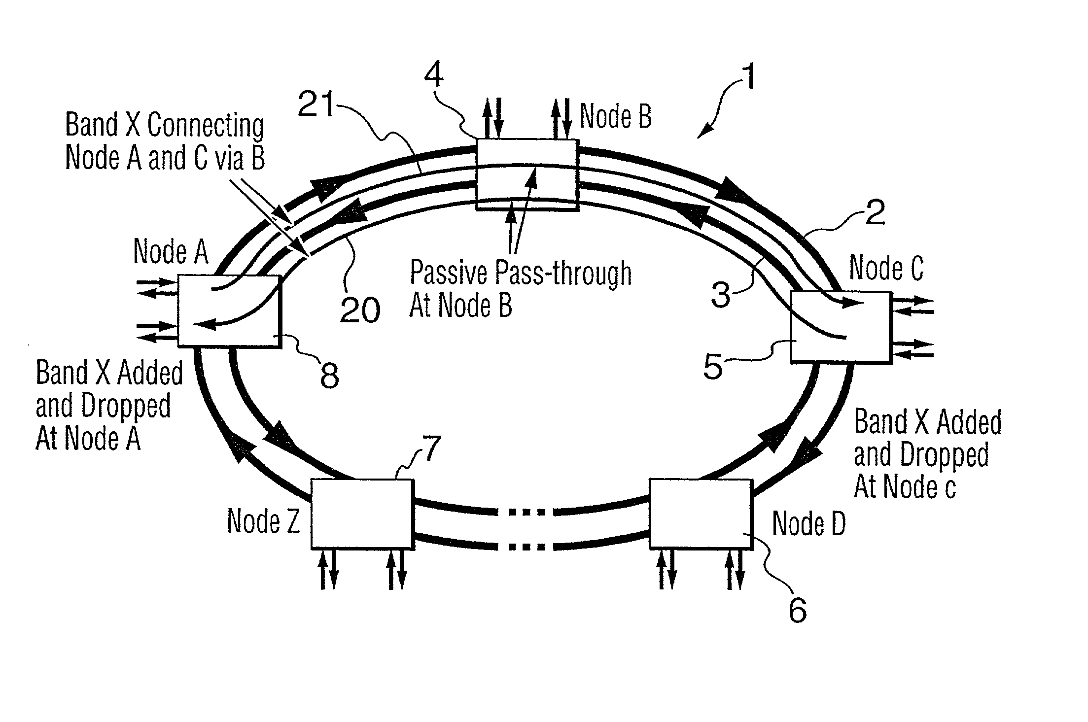
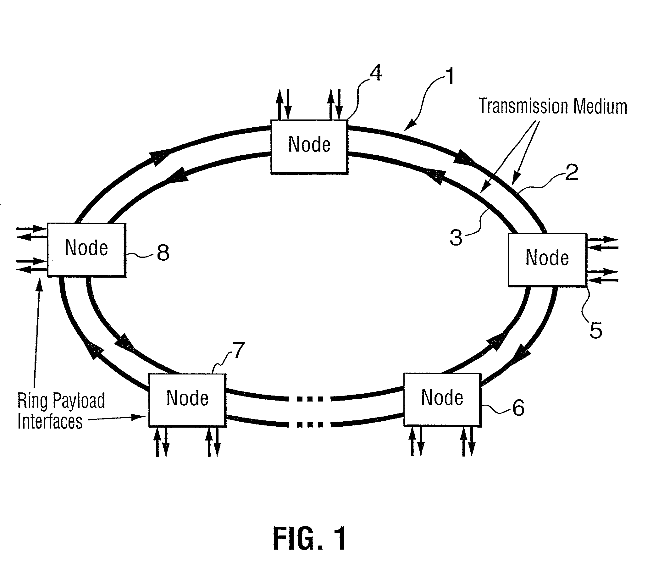
[0039] Referring now to FIG. 1, a WDM (Wavelength division Multiplexed) ring network generally referenced I consists of two counter rotating rings 2, 3 containing a plurality of nodes 4, 5, 6, 7, 8 providing interfaces to the rings 2, 3. It will be understood that FIG. 1 shows the physical layout of the network. The rings 2, 3 physically consist of optical fibers, which are capable of carrying multiple wavelengths generated by lasers in the nodes. The interconnectivity between the nodes is provided by WDM connections in a manner to be described.

[0040] Each ring may carry, for example, 16 or 32 wavelengths divided into eight bands, which provide the interconnectivity between the nodes. Typically there are either two or four wavelengths per band. With eight bands, there are therefore a total of 16 wavelengths per ring for two wavelengths per band or 32 wavelengths in the case of four wavelengths per band, for example, spaced at 1.6 nm with a guard band of 3.2 nm for a total spacing of...


PUM


Abstract

A communications network has a plurality of nodes interconnected by an optical transmission medium. The transmission medium is capable of a carrying a plurality of wavelengths organized into bands. A filter at each node for drops a band associated therewith and passively forwards other bands through the transmission medium. A device is provided at each node for adding a band to the transmission medium. Communication can be established directly between a pair of nodes in the network sharing a common band without the active intervention of any intervening node. This allows the network to be protocol independent. Also, the low losses incurred by the passive filters permit relatively long path lengths without optical amplification.

Description

[0001] This is a divisional application of U.S. patent application Ser. No. 09 / 372,576, filed Aug. 12, 1999, which is a divisional of U.S. patent application Ser. No. 08 / 917,784, filed Aug. 27, 1997.FIELD OF THE INVENTION[0002] The present invention relates to a method and apparatus for establishing communication over an optical network employing wavelength division multiplexing.BACKGROUND OF THE INVENTION[0003] The ever-increasing demand for bandwidth has spurred the growth of high speed transport networks. Currently, the key standard for use in such networks is SONET, which is an acronym for Synchronous Optical Network. The SONET standard defines a hierarchy of optical transmission rates over point-to-point and ring network topologies. For example, the SONET optical carrier--level 3 (OC-3) transmits at 1 55 Mb / s and OC-12 transmits at 622 Mb / s.[0004] SONET was developed to provide a survivable transport infrastructure that could carry a range of different payload protocols and pay...

Claims


Application Information

Patent Timeline
IPC IPC(8): H04J14/00H04B10/00H04B10/032H04B10/077H04B10/079H04B10/27H04B10/275H04B10/29H04B10/291H04B10/54H04B10/548H04B10/572H04J14/02H04Q3/52H04Q11/00
CPCH04J14/0206H04J14/0209H04J14/0212H04J14/0213H04J14/0226H04J14/0227H04J14/028H04J14/0282H04J14/0283H04J14/0284H04J14/0289H04J14/0291H04J14/0298H04Q11/0062H04J14/0241H04J14/0246H04J14/025
Inventor MILTON, DAVIDVALIS, TOMASTOTTI, GINOLIU, KEXINGPIGEON, MICHEL
Owner CIENA
Why Eureka
Try Eureka