Tunable filter

a filter and tunable technology, applied in the field of tunable filters, can solve the problems of difficult film application to the band-pass filter, difficult to increase the wavelength variable range, and change the thickness of the dielectric film, and achieve the effect of high diffraction efficiency

Inactive Publication Date: 2002-09-12
ANDO ELECTRIC CO LTD
View PDF0 Cites 16 Cited by
  • Summary
  • Abstract
  • Description
  • Claims
  • Application Information

AI Technical Summary

Benefits of technology

0019] An object of the present invention is to provide a tunable filter capable of obtaining high diffraction efficiency no matter how a polarization state of incident light changes while obtaining a wide wavelength variable range using a diffraction grating as a wavelength selection element.

Problems solved by technology

In addition, since a PDL (polarization dependent loss) becomes worse, it is difficult to increase a wavelength variable range (the order of several tens nm under present circumstances).
However, it is difficult to make film application to the band-pass filter so that the thickness of the dielectric film changes in the slide direction.
However, since the diffraction grating generally has polarization characteristics (diffraction efficiency varies greatly depending on an incident polarized wave), there is a problem that a PDL (polarization dependent loss) is large.

Method used


Image

  • Tunable filter
  • Tunable filter
  • Tunable filter

Examples


first embodiment

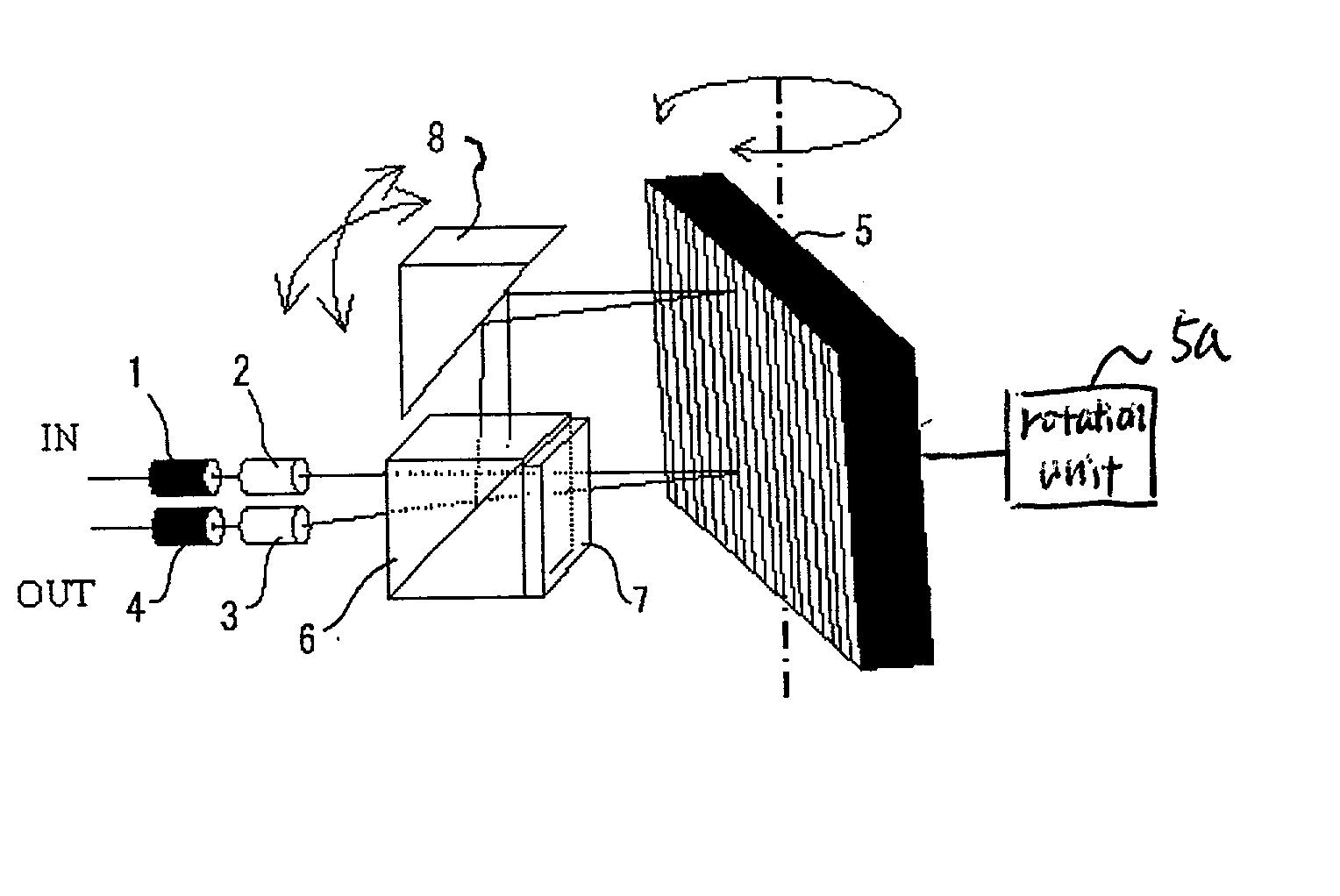
[0048] FIG. 1 is a diagram showing a configuration of a tunable filter using a diffraction grating of the invention.

[0049] Numeral 1 is an input side optical fiber, numeral 2 is an input side condenser lens, numeral 3 is an output side condenser lens, numeral 4 is an output side optical fiber. The condenser lenses 2 and 3 may be a GRIN lens (gradient index lens).

[0050] Numeral 5 is a diffraction grating, and the diffraction grating is constructed rotatably as shown in the drawing in order to change an angle of incidence of light passing through the condenser lens 2. The diffraction grating is rotated by a rotation unit 5a.

[0051] Numeral 6 is a cube type polarizer, and numeral 7 is a polarization rotator. The polarization rotator includes a half-wave plate or a garnet thick film. As the wave plate, a zero-order wave plate capable of use at a wide wavelength band is preferable.

[0052] Numeral 8 is a mirror which is provided in order to output light from the polarizer 6 to the diffracti...

second embodiment

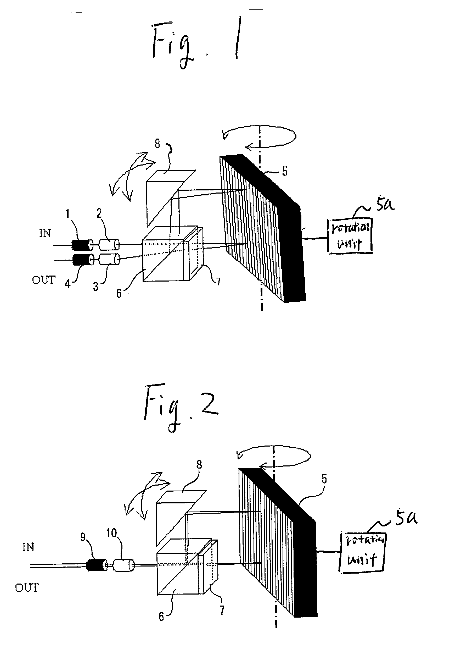
[0060] FIG. 2 is a diagram showing a configuration of a tunable filter using a diffraction grating of the invention.

[0061] Numeral 9 is a two-core fiber for input side light and output light, and numeral 10 is a condenser lens.

[0062] The condenser lens 10 may be a GRIN lens (gradient index lens).

[0063] Numeral 5 is a diffraction grating, and the diffraction grating is constructed rotatably as shown in the drawing in order to change an angle of incidence of light passing through the condenser lens 10. The diffraction grating is rotated by a rotation unit 5a.

[0064] Numeral 6 is a cube type polarizer, and numeral 7 is a polarization rotator. The polarization rotator includes a half-wave plate or a garnet thick film, and as the wave plate, a zero-order wave plate capable of use at a wide wavelength band is desirable.

[0065] Numeral 8 is a mirror which is provided in order to output light from the polarizer 6 to the diffraction grating 5 and also return the diffracted light to the polariz...

third embodiment

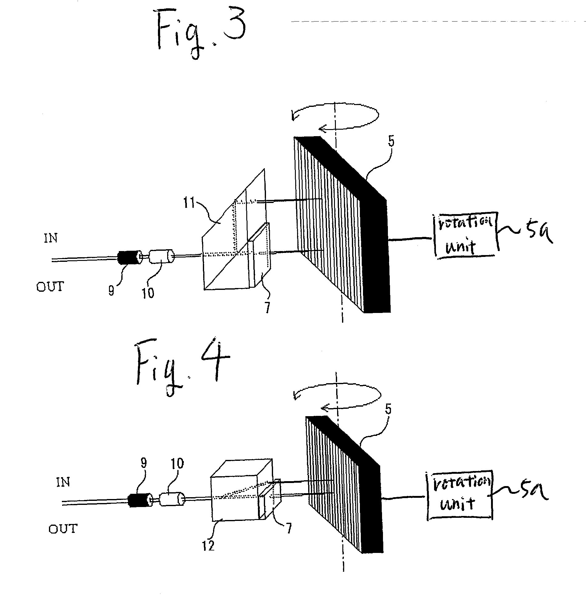
[0070] FIG. 3 is a diagram showing a configuration of a tunable filter using a diffraction grating of the invention.

[0071] Numeral 9 is a two-core fiber for input side light and output light, and numeral 10 is a condenser lens.

[0072] The condenser lens 10 may be a GRIN lens (gradient index lens).

[0073] Numeral 5 is a diffraction grating, and the diffraction grating is constructed rotatably as shown in the drawing in order to change an angle of incidence of light passing through the condenser lens 10. The diffraction grating is rotated by a rotation unit 5a.

[0074] Numeral 11 is a parallelogram prism type polarizer and has a function combining the cube type polarizer 6 and the mirror 8 in FIG. 2.

[0075] Numeral 7 is a polarization rotator, and the polarization rotator includes a half-wave plate or a garnet thick film, and as the wave plate, a zero-order wave plate capable of use at a wide wavelength band is desirable.

[0076] FIG. 7 is a diagram showing a concept of splitting input light...


PUM


Abstract

A tunable filter includes a polarizer, a polarization rotator, a diffraction grating and a diffraction grating adjustor. The polarizer polarizes a light beam and splits the light beam into first and second light beams. The polarization rotator rotates a plane of polarization of the first light beam at 90.degree. to generate a rotated light beam. The diffraction grating receives the rotated light beam and the second light beam. The diffraction grating adjustor adjusts the diffraction grating to change incident angles of the rotated light beam and second light beam.

Description

BACKGROUND OF THE INVENTION[0001] 1. Field of the Invention[0002] The present invention relates to a tunable filter using a diffraction grating as a wavelength selection element.[0003] 2. Description of the Related Art[0004] FIGS. 9 to 11 shows conventional tunable filters for selectively passing only a light beam having a predetermined wavelength.[0005] The conventional tunable filters will be described below with reference to the drawings.[0006] FIG. 9 is an example using a band-pass filter. Numeral 21 is an input side optical fiber, numeral 22 is an input side condenser lens, numeral 23 is an output side condenser lens and numeral 24 is an output side optical fiber, and numeral 25 is a band-pass filter. A dielectric film for passing only a light beam having a particular wavelength is applied to a glass plate.[0007] The band-pass filter is rotatable as shown in the drawing in order to change an angle of incidence of the light beam passing through the condenser lens 22.[0008] In th...

Claims


Application Information

Patent Timeline
Patent Type & Authority Applications(United States)
IPC IPC(8): G01J3/18G01J3/02G01J3/06G01J3/26G02B5/18G02B5/30G02B6/34G02B26/00
CPCG01J3/02G01J3/0224G01J3/0237G01J3/06G01J3/18G01J3/26G02B5/1828G02B26/00
Inventor ASAMI, KEISUKEITO, TOMOO
Owner ANDO ELECTRIC CO LTD
Why Eureka
Try Eureka