
Head supporting device and disk drive using the same

a technology of supporting device and disk drive, which is applied in the field of supporting device, can solve the problems of slider jumping off the magnetic recording medium, affecting the operation reducing the amount of so as to achieve even faster rotational movement and reduce the effect of undesired vibration of the support arm

Inactive Publication Date: 2002-09-12
WESTERN DIGITAL TECH INC
View PDF4 Cites 14 Cited by
  • Summary
  • Abstract
  • Description
  • Claims
  • Application Information

AI Technical Summary

Benefits of technology

[0028] As a result, there is provided the head supporting device having an extremely high resistance to shock, high responsivity, and capability of making a high speed access, even if a shock is impressed from the outside, since a part constituting the support arm can be formed with the highly rigid material and the thrusting force of the resilient means to the slider can be set freely as desired, and also since the resonance frequency can be increased, because of the structure in which the part having a rigid body and the other part having resiliency can be provided independently with respect to each other.
[0057] Moreover, in the disk drive of this invention, a center of gravity of a portion held by the resilient means is generally in alignment with a point of intersection between a rotational axis of the support arm in the radial direction of the recording medium and a rotational axis of the recording medium in the direction perpendicular to the writing surface of the recording medium. This can reduce undesired vibrations of the support arm to a minimum level possible even when there are any shocks and the like from the outside.

Problems solved by technology

This causes the head supporting device to take some time to get itself settled (stabilized) from the vibrating mode, thereby placing a limitation on reduction of the access time.
In addition, since the conventional head supporting device has its center of gravity in a position nearer to the magnetic head than the plate spring, there occurs a phenomenon that the slider jumps off the magnetic recording medium, because the slider loses its balance between the levitational force of the airflow generated by spinning of the magnetic recording medium and the thrusting force placed by the head supporting device for shifting the slider toward the magnetic recording medium when a strong impact and the like is impressed upon the magnetic disk drive from the outside.
Thus, possibilities exist that the slider hit the magnetic recording medium, and causes a magnetic damage and / or mechanical damage to the magnetic recording medium.
Moreover, there has been no other means than discarding the suspension if the desired load could not be obtained due to a deviation in forming the plate spring.
Therefore, it results in sacrifice of a resonance performance of the suspension when the load adjustment is made afterward.
The problems described above are not unique to the magnetic disk drive, but any other disk drives having levitating type head such as optical disk drives, magneto-optic disk drives, for instance, also have similar problems.

Method used


Image

  • Head supporting device and disk drive using the same
  • Head supporting device and disk drive using the same
  • Head supporting device and disk drive using the same

Examples


first exemplary embodiment

[0071] As a first exemplary embodiment, an operating principle of a head supporting device of the present invention will be described first, using a magnetic disk drive as an example.

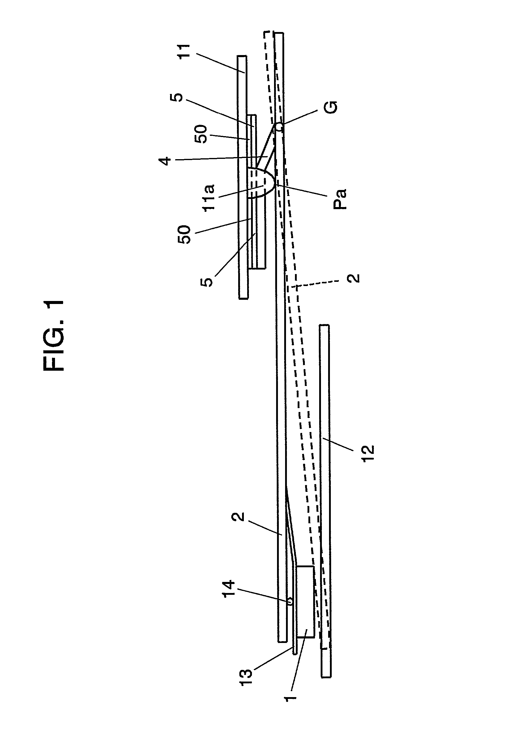
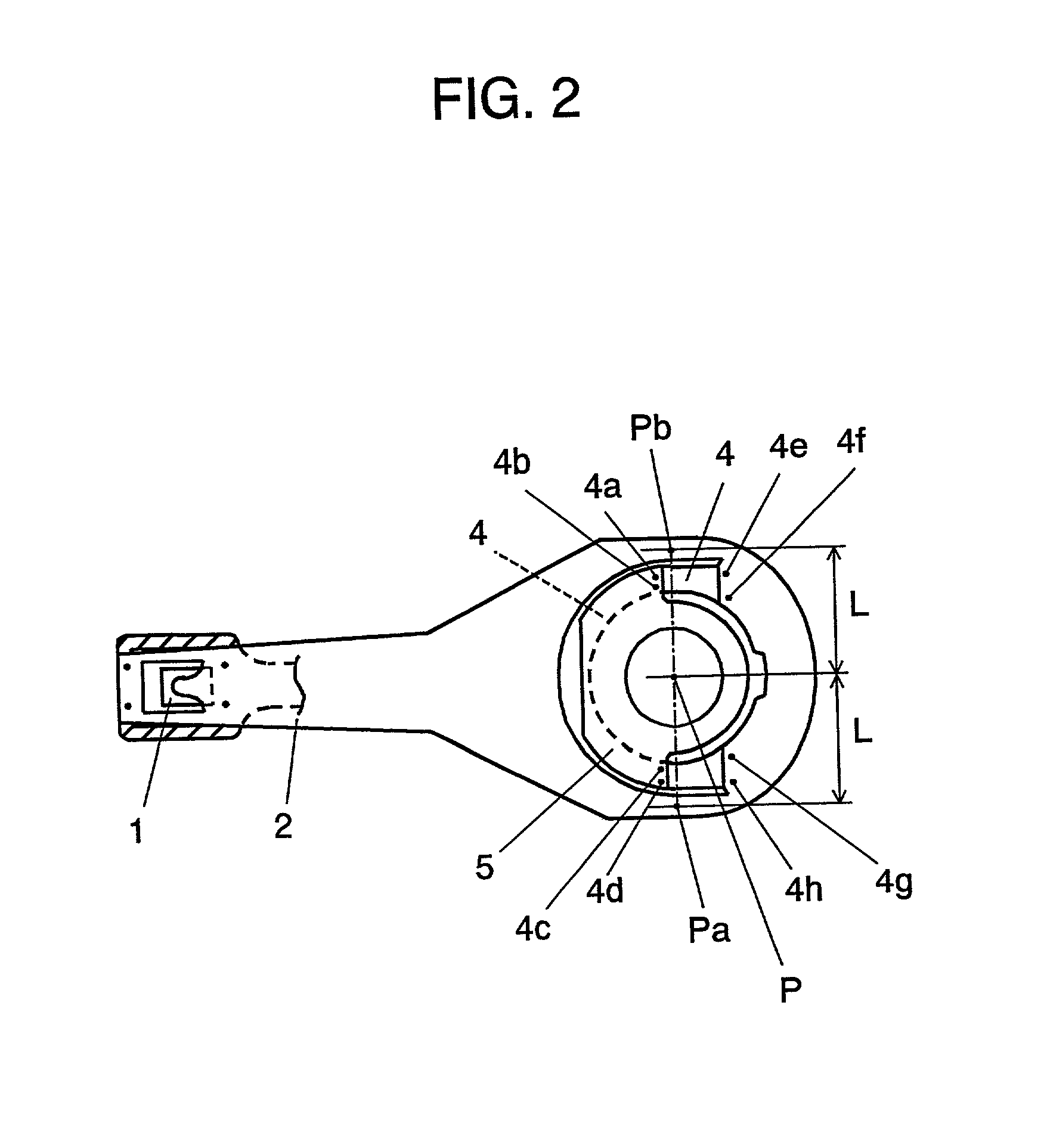
[0072] FIG. 1 is a side view depicting a general structure of a head supporting device, for the purpose of showing the operating principle of the head supporting device of this invention, FIG. 2 is a plan view, and FIG. 3 is an exploded structural illustration of the same.

[0073] In FIG. 1 and FIG. 2, slider 1 provided with a magnetic head (not show in the figures) on an underside surface thereof is mounted to an underside surface at one end of support arm 2, which is then fixed at the other end to one end portion of plate spring 4, as shown in the figures. The other end portion of the plate spring 4 is fixed to spring fixation member 5, which in turn is fixed to pivot pedestal 11 through spacer 50.

[0074] Accordingly, the support arm 2 is now in a configuration that it is flexibly secured to the pivot pe...

second exemplary embodiment

[0094] A structure of the head supporting device of this invention that achieves the operating principle shown in the first exemplary embodiment will be disclosed next as a second exemplary embodiment of this invention.

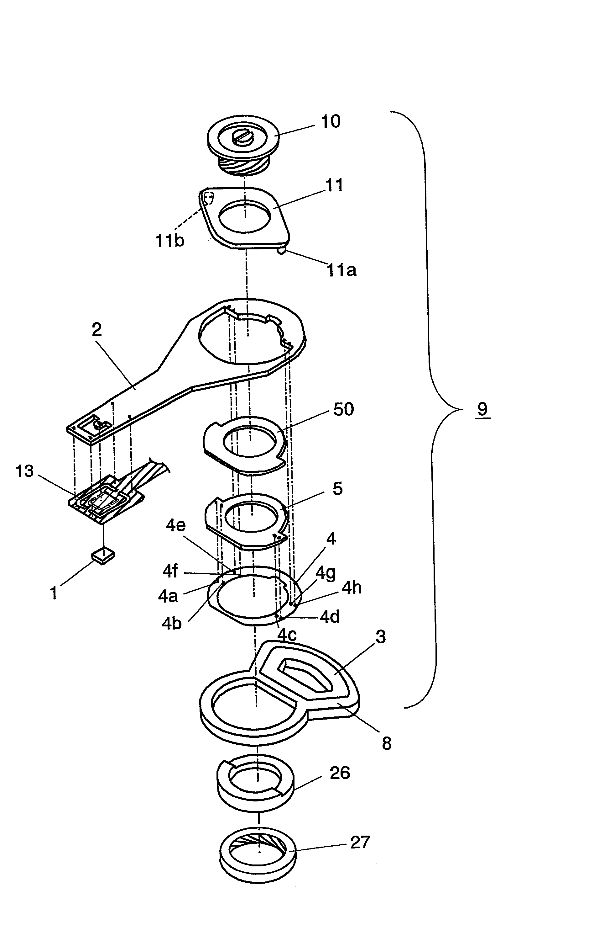
[0095] FIG. 3 is an exploded perspective view depicting the structure of the head supporting device of this invention, FIG. 4 is also an exploded perspective view, and FIG. 5 is a side view showing a main portion in the vicinity of a bearing unit of the same.

[0096] In the head supporting device 9, plate spring 4 of an annular shape and spring fixation member 5 also of an annular shape are connected by welding at points 4a, 4b, 4c and 4d, as shown in FIG. 3 and FIG. 4. Support arm 2 and the plate spring 4 are connected also by welding at points 4e, 4f, 4g and 4h. The support arm 2 is connected to coil holder 8 provided with coil 3, so as to be rotatable by a voice coil motor in a radial direction of magnetic recording medium 12. This structure is such that the above me...

third exemplary embodiment

[0119] Referring to the accompanying figures, a structure of a disk drive of this invention will be described using a magnetic disk drive as an example of the third exemplary embodiment. FIG. 6 is a plan view depicting a structure of magnetic disk drive 23 of the present invention, and FIG. 7 is a sectional view taken along a line A-A in FIG. 6.

[0120] A structure and operation of the magnetic disk drive of the invention and its head supporting device will be described first.

[0121] FIG. 6 and FIG. 7 illustrate the magnetic disk drive when it is not operating, i.e. in a state that a magnetic recording medium is not spinning.

[0122] Magnetic disk drive 23 of the present invention is provided with head supporting device 9 having support arm 2 formed unitary with a single material, as shown in FIG. 6 and FIG. 7.

[0123] The structure of the head supporting device 9 of the magnetic disk drive 23 of this invention is described hereinafter with reference to FIG. 6, FIG. 7 and FIG. 8. FIG. 8 is...


PUM

PropertyMeasurementUnit
thicknessaaaaaaaaaa
heightaaaaaaaaaa
thicknessaaaaaaaaaa

Abstract

A head supporting device comprises a support arm and a head mounted to an underside surface at one end of the support arm. The support arm is disposed in a rotatable manner about a bearing unit in a radial direction of a recording medium as well as a perpendicular direction with respect to a writing surface of the recording medium, and the support arm is provided with resilient means for imposing upon itself with a thrusting force in a direction toward the recording medium. Because of this structure, a portion serving as the support arm can be formed with a material of high rigidity, the thrusting force of the resilient means upon the slider can be set freely as desired, and its resonance frequency can be increased, thereby providing the head supporting device with an extremely high resistance to shock, and high responsivity with capability of making a high speed access.

Description

FIELD OF THE INVENTION[0001] The present invention relates to a head supporting device for levitating type head, and a disk drive using the same such as a magnetic disk drive, optical disk drive, magneto-optic disk drive, and the like.BACKGROUND OF THE INVENTION[0002] With reference to the accompanying drawing, described hereinafter pertains to a head supporting device of the prior art employed in a magnetic disk drive such as hard disk drive, as an example of the conventional head supporting device of a disk drive having a levitating type head.[0003] FIG. 11 is a plan view showing a structure of a head supporting device of the prior art for a magnetic disk drive, and a relation between the head supporting device and a magnetic recording medium.[0004] In FIG. 11, head supporting device 108 has such a structure that comprises suspension 102 of a comparatively low rigidity, plate spring 103, and support arm 104 of a comparatively high rigidity, and that the suspension 102 is provided ...

Claims


Application Information

Patent Timeline
Patent Type & Authority Applications(United States)
IPC IPC(8): G11B5/48G11B11/105
CPCG11B5/4806G11B5/4826G11B11/1055
Inventor KUWAJIMA, HIDEKISAKAMOTO, KENICHIMIYAMOTO, MAKOTO
Owner WESTERN DIGITAL TECH INC
Learn More