Optical fiber with reduced cladding-mode loss

a technology of optical fibers and cladding modes, applied in the field of optical fibers, can solve the problems of cladding-mode coupling loss (cmcl), degrade the performance of bragg gratings, and thus the overall system performance, and achieve the effect of reducing the amount of coupling, reducing the loss of cladding-mode coupling, and attenuating the power propagation

Inactive Publication Date: 2002-09-12
VERRILLON
View PDF0 Cites 18 Cited by
  • Summary
  • Abstract
  • Description
  • Claims
  • Application Information

AI Technical Summary

Benefits of technology

0006] The present invention is directed toward attenuating the power propagating in the cladding of an optical fiber, thereby reducing the amount of coupling between the cladding mode power reflected at the Bragg grating interface with the forward propagating core modes. In other words, the cladding-mode coupling loss is reduced.

Problems solved by technology

The backward-propagating cladding modes couple with the forward-propagating core modes resulting in cladding-mode coupling loss (CMCL).
CMCL degrades the performance of the Bragg grating, and thus the performance of the overall system.

Method used


Image

  • Optical fiber with reduced cladding-mode loss
  • Optical fiber with reduced cladding-mode loss
  • Optical fiber with reduced cladding-mode loss

Examples


Embodiment Construction

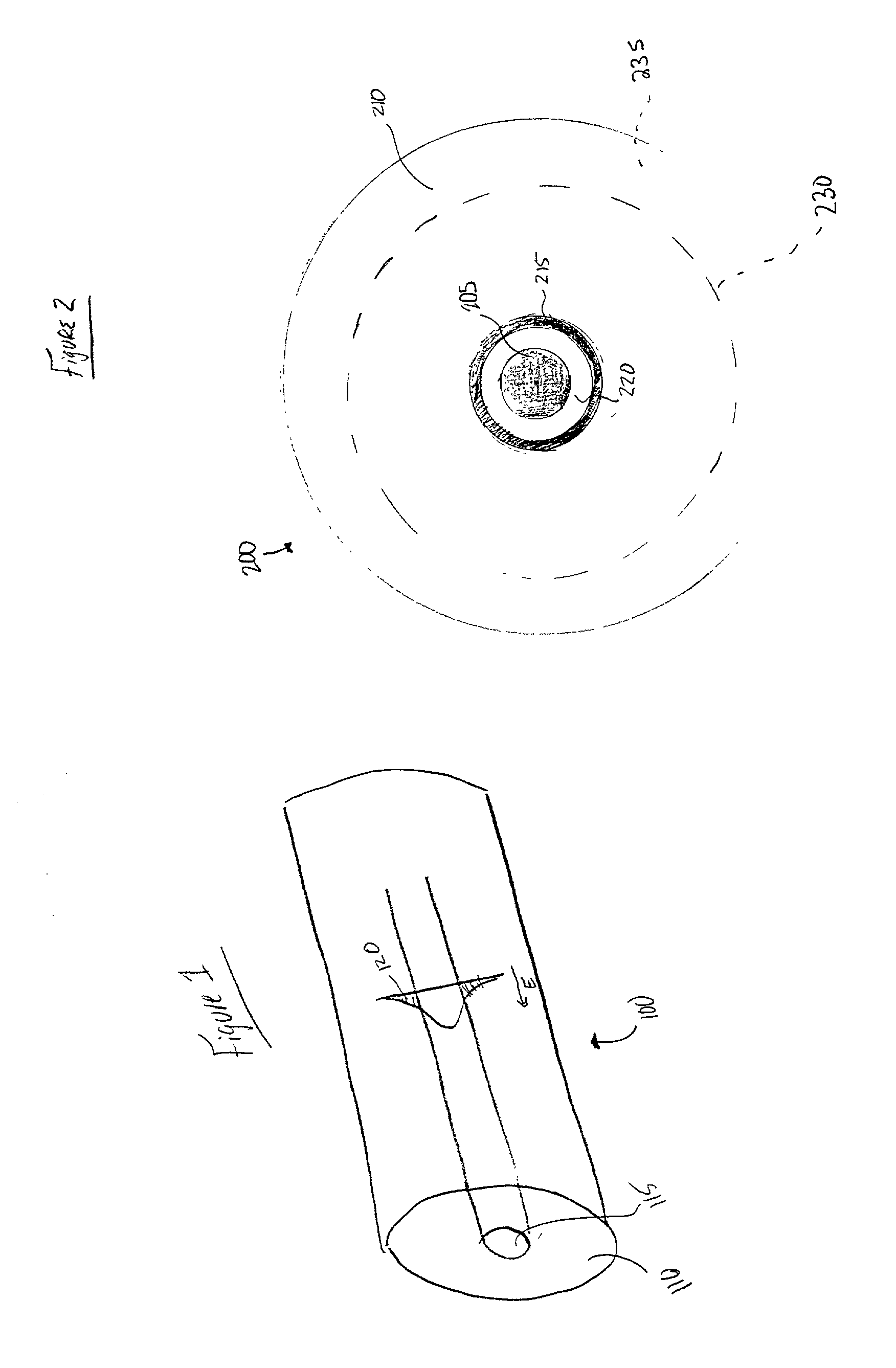
[0014] In most light-carrying optical fibers, there exists an interface between the core and the surrounding medium, typically a glass cladding. This structure supports a number of cladding modes (i.e., signal power that propagates through the cladding) as well as the core mode, which propagates through the fiber core. With reference to FIG. 1, a typical optical fiber 100 includes a cladding 110 surrounding a core 115. FIG. 1 depicts the energy profile of a single-mode beam, having a gaussian energy distribution, propagating through core 115. Although the bulk of the propagating signal power remains within the core, a portion, the "tail" 120, extends radially out of the core and propagates within the cladding 110. Although the gaussian profile is asymptotic, tail 120 is considered effectively to extend to mode field diameter-i.e., the point at which the power level becomes negligible (less than the noise level).

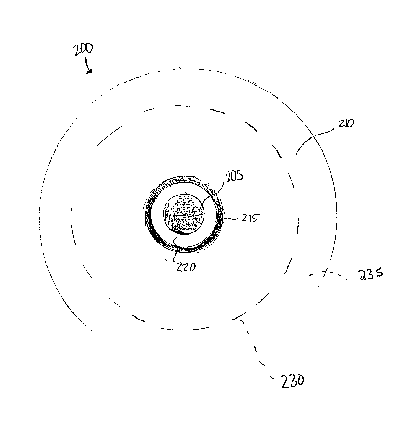
[0015] With reference to FIG. 2, an optical fiber 200 in accordance with...


PUM


Abstract

The invention is directed toward an optical fiber that reduces the cladding mode coupling loss (CMCL) therein. The fiber includes a core, a cladding concentrically surrounding the core, and at least one lossy region concentrically surrounding the core. The lossy region is disposed within the cladding and is slightly displaced radially from the core.

Description

CROSS-REFERENCE TO RELATED APPLICATIONS[0001] This application claims the benefits of U.S. Provisional Patent Application No. 60 / 275,057, filed on Mar. 12, 2001, the entire disclosure of which is hereby incorporated by reference.FIELD OF THE INVENTION[0002] The invention relates generally to optical fibers and more specifically to optical fibers with reduced cladding-mode losses.BACKGROUND OF THE INVENTION[0003] Fiber Bragg gratings are used in various wavelength-dependent signal-processing applications, most notably in wavelength-division multiplexing (WDM) and dense wavelength-division multiplexing (DWDM) systems. In these systems, light of multiple wavelengths propagates through a transmission medium, typically an optical fiber. Because the wavelengths are spaced apart spectrally and do not interfere with each other, they represent separate communication channels that can be independently modulated to carry information. To select a particular channel, its wavelength must be extra...

Claims


Application Information

Patent Timeline
Patent Type & Authority Applications(United States)
IPC IPC(8): G02B6/02G02B6/036G02B6/10G02B6/34H01S3/067H01S3/094
CPCG02B6/02G02B6/02052G02B6/021G02B6/03633G02B6/03694G02B6/105H01S3/06708H01S3/06729H01S3/094003
Inventor SOUFIANE, ABDELOUAHED
Owner VERRILLON
Why Eureka
Try Eureka