
Turbine vane assembly including a low ductility vane

Inactive Publication Date: 2002-09-12
GENERAL ELECTRIC CO
View PDF0 Cites 40 Cited by
  • Summary
  • Abstract
  • Description
  • Claims
  • Application Information

AI Technical Summary

Benefits of technology

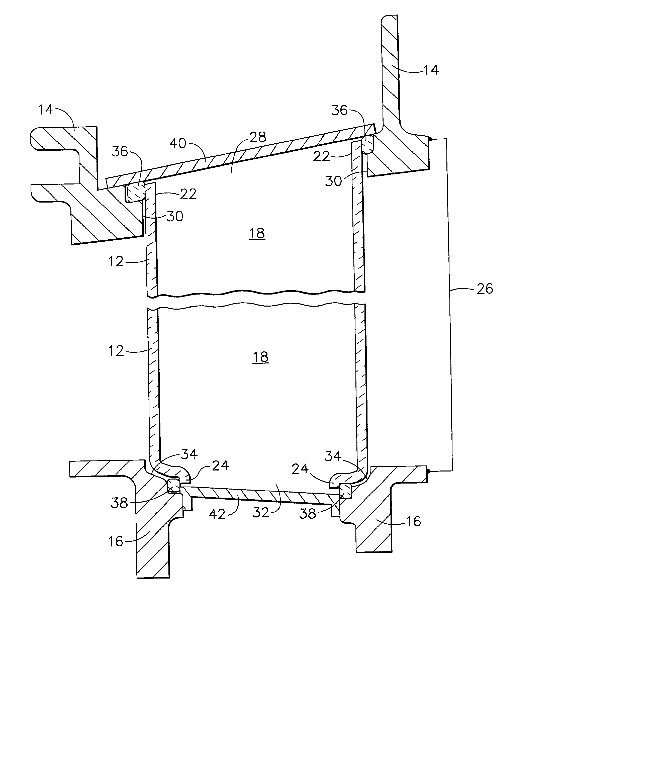
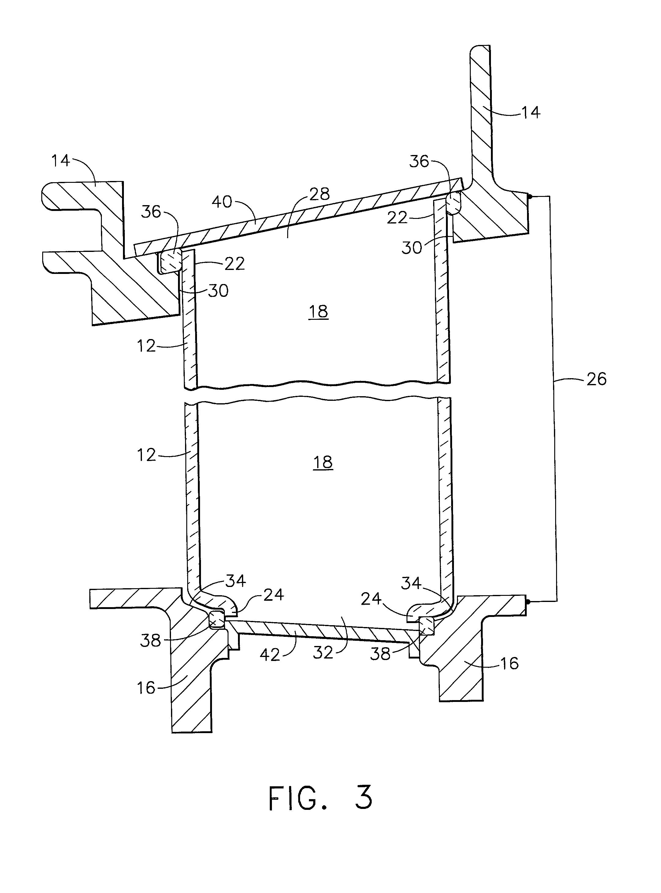
0006] In one form, the present invention provides a turbine vane assembly comprising an outer vane support, an inner vane support in a fixed spaced apart position from the outer vane support, and at least one airfoil shaped vane supported between the outer and inner vane supports. The vane is of a low ductility material, for example based on a ceramic matrix composite or an intermetallic material, having a room temperature ductility no greater than about 1%. The outer and inner vane supports are of material having a r

Problems solved by technology

From evaluation of service operated turbine nozzles made of coated high temperature superalloys, it has been observed that the strenuous, high temperature, erosive and corrosive conditions existing in the engine flow path downstream of a gas turbine engine combustion section can result in degradation of the environmental resistant coating and / or alloy substrate structure of vanes of the nozzle.

Method used


Image

  • Turbine vane assembly including a low ductility vane
  • Turbine vane assembly including a low ductility vane
  • Turbine vane assembly including a low ductility vane

Examples


Embodiment Construction

[0014] Certain ceramic base and intermetallic type of high temperature resistant materials, including monolithic as well as intermetallic base and ceramic based composites, have been developed with adequate strength properties along with improved environmental resistance to enable them to be attractive for use in the strenuous type of environment existing in hot sections of a turbine engine. However, such materials have the common property of being very low in tensile ductility compared with high temperature metal alloys generally used for their support structures. In addition, there generally is a significant difference in coefficients of thermal expansion (CTE) between such materials and alloys, for example between low ductility ceramic matrix composites (CMC) or intermetallic materials based on NiAl, and typical commercial Ni base and Co base superalloys currently used as supports in such engine sections.

[0015] If such low ductility materials are rigidly supported by such high te...


PUM


Abstract

At least one airfoil shaped vane made of a low ductility material, for example a ceramic base material such as a ceramic matrix composite or an intermetallic material such as NiAl material, is releasably carried in a turbine vane assembly including inner and outer vane supports by at least one high temperature resistant compliant seal. The seal isolates the vane from at least one of the vane supports and allows independent thermal expansion and contraction of the vane in respect to the support.

Description

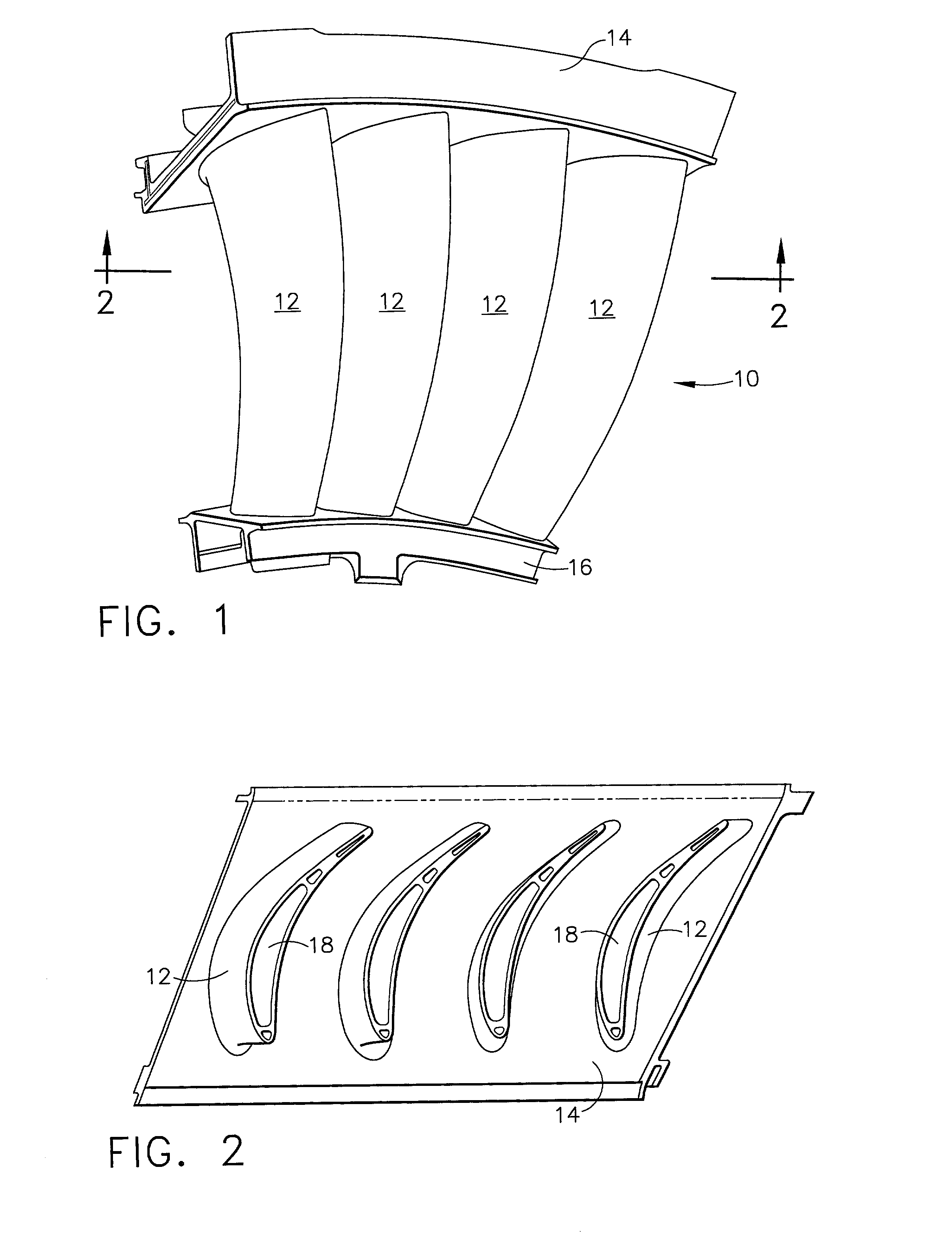
BACKGROUND OF THE INVENTION[0002] This invention relates to turbine vane assemblies, for example of the type used in gas turbine engines. More particularly in one embodiment, it relates to a turbine vane assembly including at least one low ductility vane carried at least in part by a compliant seal to enable expansion and contraction of the vane independently from at least one of spaced apart metal supports or bands.[0003] Components in sections of gas turbine engines operating at elevated temperatures in a strenuous, oxidizing type of gas flow environment typically are made of high temperature superalloys such as those based on at least one of Fe, Co, and Ni. In order to resist degradation of the metal alloy of such components, it has been common practice to provide such components with a combination of fluid or air cooling and surface environmental protection or coating, of various widely reported types and combinations.[0004] One type of such a gas turbine engine component is a t...

Claims


Application Information

Patent Timeline
IPC IPC(8): F01D5/30F01D9/02F01D9/04
CPCF01D5/3084F01D9/042
Inventor DAROLIA, RAMGOPALKETZER, JAMES ANTHONY
Owner GENERAL ELECTRIC CO
Learn More