Emissivity-change-free pumping plate kit in a single wafer chamber

a technology of emissivity change and pumping plate, which is applied in the field of emissivity change-free pumping plate kit in a single wafer chamber, can solve the problems of powder formation and other problems, and achieve the effects of reducing powder formation, preventing emissivity change, and preventing emissivity change in the chamber

Inactive Publication Date: 2002-09-12
APPLIED MATERIALS INC
View PDF24 Cites 12 Cited by
  • Summary
  • Abstract
  • Description
  • Claims
  • Application Information

AI Technical Summary

Benefits of technology

0009] The emissivity-change-free pumping plate kit disclosed herein may be used for preventing emissivity change during wafer processing by providing, in part, a gas purge to the chamber to prevent residual or powder formation on the pumping and face plates, thereby preventing an emissivity change in the chamber. More specifically, the gas purge may flow from the bottom purge or from the showerhead. Furthermore, even with a gas purge, powder formation may occur. Therefore, to reduce powder formation on the pumping and face plates, minimization of exposure to the gas is desirable, i.e., one can facilitate gas exiting between the pumping plate and face plate by using this top open pumping plate kit. The kit may also be used for providing optimal film thickness uniformity during wafer processing.
0010] The invention further discloses a pumping plate having an aft skirt that acts to absorb heat radiated off the susceptor. The pumping plate has a wafer loading slot in the skirt that faces a wafer loading structure (slit valve) in the process chamber. Heat radiating off the susceptor, passing through the wafer loading slot in the pumping plate, enters the slit valve. The slit valve acts to absorb more heat from the susceptor than do other areas of the chamber interior. The susceptor in the area of the slit valve receives less reflected heat and as a result, the susceptor in this area can be cooler. A non-uniformly heated susceptor can effect film deposition onto the wafer and to compensate, a skirt is added to the pumping plate. The skirt is slotted, i.e. has holes to improve absorption by the skirt from heat radiating off the susceptor. The skirt reduces heat reflected back to the susceptor from the chamber walls and this has the effect of balancing the heat loss into the slit valve. With a thermally balanced susceptor, uniform film deposition onto the wafer can result.

Problems solved by technology

Furthermore, even with a gas purge, powder formation may occur.

Method used


Image

  • Emissivity-change-free pumping plate kit in a single wafer chamber
  • Emissivity-change-free pumping plate kit in a single wafer chamber
  • Emissivity-change-free pumping plate kit in a single wafer chamber

Examples


Embodiment Construction

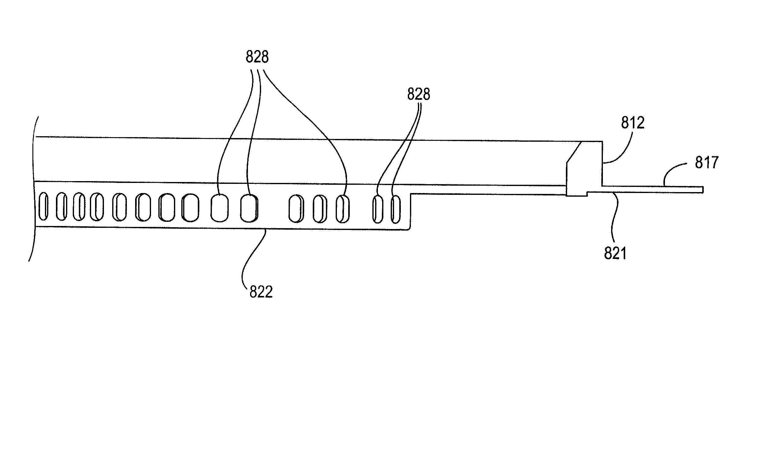
[0032] Disclosed herein is an emissivity-change-free pumping plate kit used for preventing the emissivity change during wafer processing which leads to process drift and particles. Problems such as powder formation in the inner chamber and blockage of pumping holes by powder are also addressed herein.

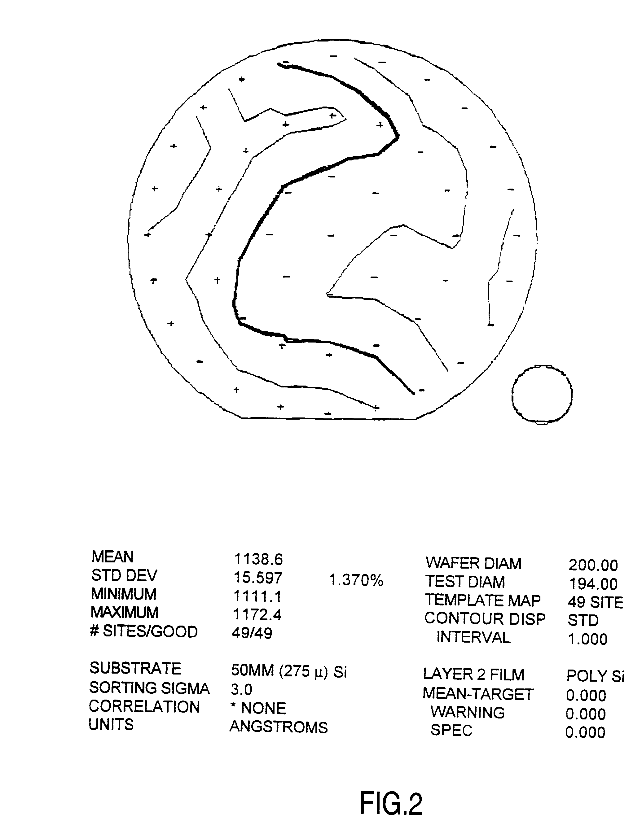
[0033] In the prior art for silicon (Si) deposition, a standard pumping plate is used, which has pumping holes for gas to flow through. FIG. 2 shows that with the standard pumping plate, the uniformity is 1.37%. During the deposition, yellow or black powders tend to accumulate on the pumping and face plates, which would cause emissivity change in the chamber and further temperature change. In order to improve the uniformity and meanwhile prevent emissivity change, a top open pumping plate is used in the present invention (see FIG. 5). With the top of the pumping plate fully open, purge gas can easily flow into the pumping channel and further eliminate the powder from the chamber. FIG. 3...


PUM

PropertyMeasurementUnit
temperatureaaaaaaaaaa

Abstract

An apparatus that includes a pumping plate having a skirt, where the skirt contains a number of holes and a wafer access slot, and where the number of holes are sized and positioned to provide uniform heating of a susceptor.

Description

CROSS-REFERENCE TO RELATED APPLICATION[0001] This is a continuation in part of U.S. application Ser. No. 09 / 798,424, filed Mar. 2, 2001, which claims priority to U.S. Provisional Application No. 60 / 220,039, filed Jul. 21, 2000.BACKGROUND OF THE INVENTION[0002] 1. Field of the Invention[0003] The present invention relates generally to the field of semiconductor manufacturing. More specifically, the present invention relates to an emissivity-change-free pumping plate kit in a single wafer chamber.[0004] 2. Description of the Related Art[0005] Chemical vapor deposition, commonly referred to as "CVD," is one of a number of processes used to deposit thin layers of material on a semiconductor wafer, and may be based on thermal, plasma, or optically assisted decomposition, or reaction of chemicals. To process wafers in, for example, a thermal CVD process, a chamber is provided with a susceptor configured to receive a wafer. The wafer is typically placed onto and removed from the susceptor ...

Claims


Application Information

Patent Timeline
Patent Type & Authority Applications(United States)
IPC IPC(8): C23C16/44C23C16/46C23C16/455H01L21/00H01L21/205
CPCC23C16/4401C23C16/4412C23C16/45521C23C16/45591C23C16/46H01L21/67109C23C16/455
Inventor JIN, XIAOLIANGWANG, SHULINLUO, LEEHO, HENRYCHEN, STEVEN A.
Owner APPLIED MATERIALS INC
Why Eureka
Try Eureka