Digital baseband receiver in a multi-carrier power amplifier

a power amplifier and digital baseband technology, applied in the field of digital baseband receivers, can solve the problems of affecting the transmission and reception of rf signals, affecting the signal quality of proximate frequency bands,

Inactive Publication Date: 2002-09-12
COMMSCOPE TECH LLC
View PDF4 Cites 101 Cited by
  • Summary
  • Abstract
  • Description
  • Claims
  • Application Information

AI Technical Summary

Problems solved by technology

Unfortunately, in practice, physical RF power amplifiers can be non-linear and add a certain amount of unwanted distortion to a signal, which distortion is realized as IMD products.
These IMD products cause interference over in the normal operating frequency range of the amplifier, which may impede proper transmission and reception of RF signals.
Energy leakage resulting from one band spilling over into another can undesirably degrade the signal-to-noise (SNR) ratio or bit-error rate (BER) of the proximate frequency bands.
However, because the amplifier is not aligned in accordance with the actual distortion products, they may not be entirely cancelled or may leak into the output, creating unwanted byproducts.
However, such an approach would not be well suited for detecting narrowband signals such as TDMA and their associated IMD products, in part due to the wide bandwidth of the filter (1.25 MHz).
If the signals are located in a PCS frequency band (1930 to 1990 MHz), a narrowband tuner would require too much time to tune across the 60 MHz band, and a wideband tuner would not be able to detect the individual carriers of TDMA or GSM signals or their associated IMD products.

Method used


Image

  • Digital baseband receiver in a multi-carrier power amplifier
  • Digital baseband receiver in a multi-carrier power amplifier
  • Digital baseband receiver in a multi-carrier power amplifier

Examples


Embodiment Construction

[0016] Although the invention will be described next in connection with certain exemplary embodiments, it will be understood that the invention is not limited to those particular embodiments. On the contrary, the description of the invention is intended to cover all alternatives, modifications, and equivalent arrangements as may be included within the spirit and scope of the invention as defined by the appended claims.

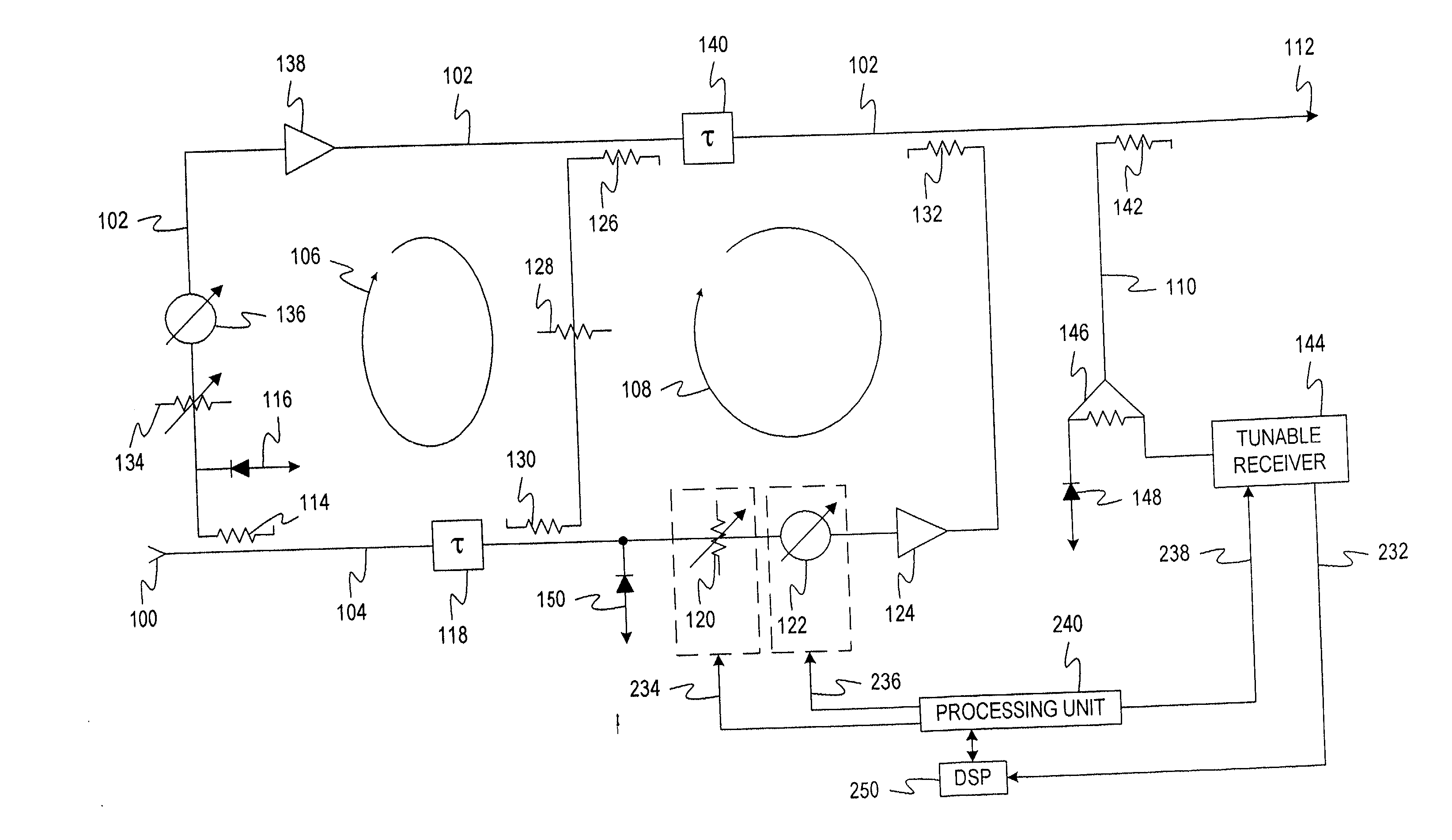
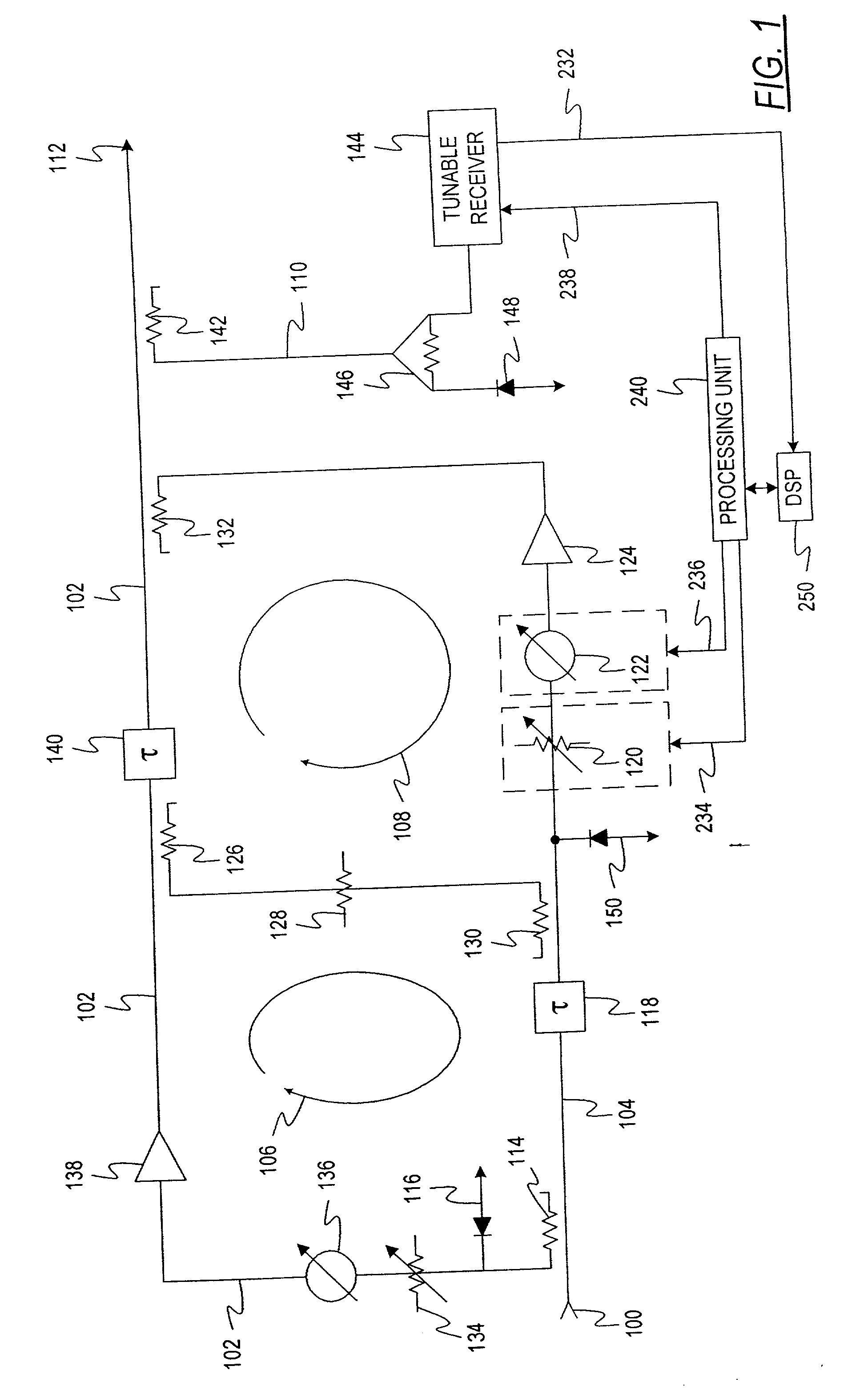
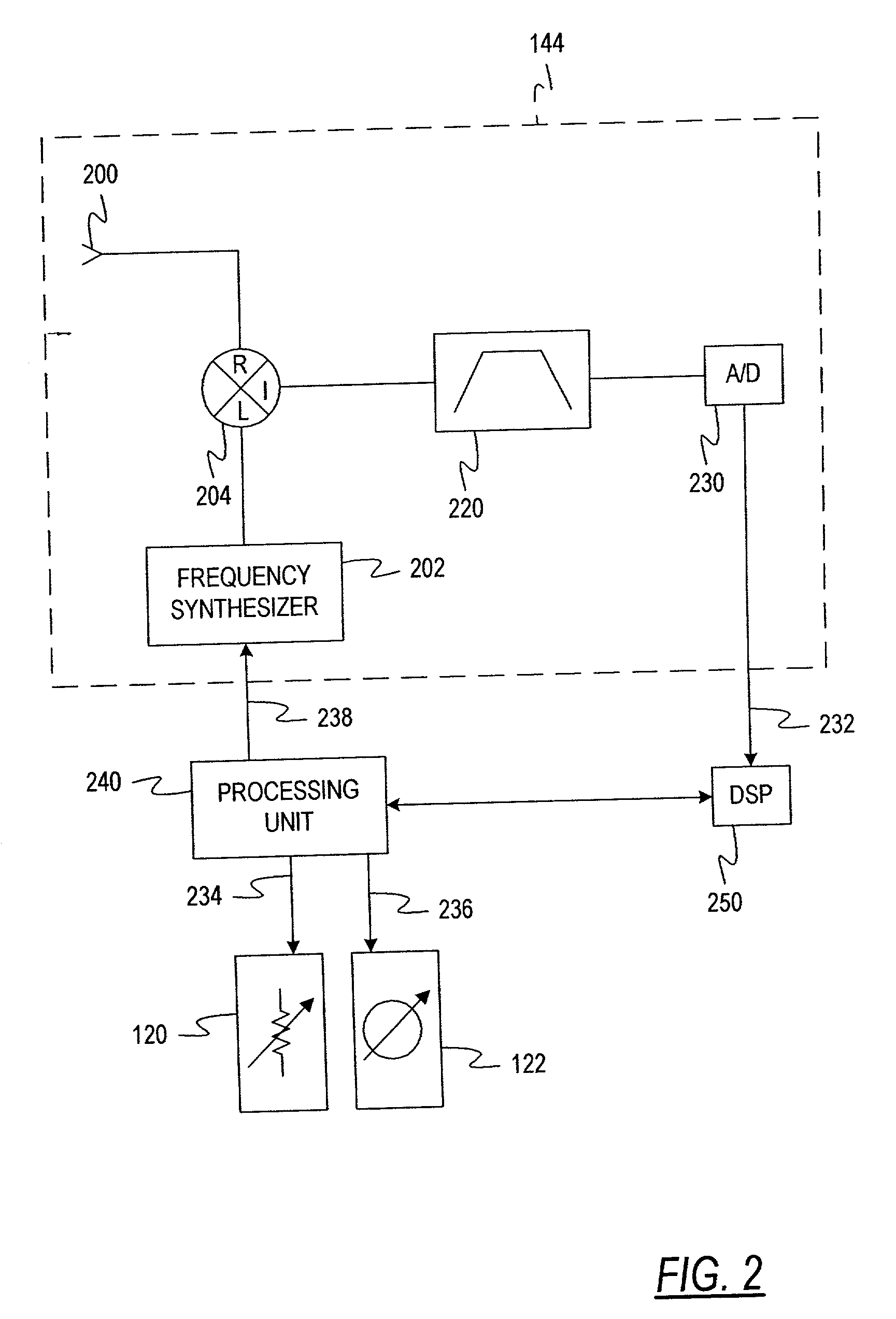
[0017] The present invention relates to an apparatus and method for locating and suppressing intermodulation distortion (IMD) products in an amplifier system. A signal path having an input and an output is configured to communicate an RF communications signal disposed in a frequency band. A tunable receiver is coupled to the signal path and configured to downconvert at least a portion of the frequency band for the RF communications signal to an Intermediate Frequency (IF) signal. A circuit arrangement is configured to convert a time domain representation of the IF sign...


PUM


Abstract

A power amplifier system and method for locating carrier frequencies across a frequency band, identifying the modulation format of each carrier, and locating and suppressing undesired intermodulation distortion (IMD) products generated by the power amplifier. The system includes an amplifier for amplifying RF carrier signals in a main signal path, a variable phase shifter and variable attenuator on a feed forward path, and a tunable receiver that digitizes a portion of the frequency band to baseband. The tunable receiver includes a tunable voltage controlled oscillator which provides an oscillating frequency to a mixer and is phase-locked to a highly stable reference oscillator. The mixer downconverts a desired RF based on the oscillating frequency to IF. A filter passes only a selected portion of the IF signals, and the filter has a passband sufficient to discern both narrowband and wideband carriers and their associated IMD products. Based on the locations of the carrier frequencies, a processing unit determines the IMD locations of the carrier frequencies, determines the IMD locations, and adjusts the variable phase shifter and variable attenuator on the feed forward path until the IMD products in the main signal path are suppressed below a desired threshold.

Description

CROSS-REFERENCE TO RELATED APPLICATIONS[0001] This application claims the benefit of U.S. Provisional Patent Application Ser. No. 60 / 273,987, filed Mar. 7, 2001 by Paul E. White et al., which application is incorporated by reference herein.FIELD OF THE INVENTION[0002] This invention relates generally to radio frequency (RF) power amplifier systems, and more particularly to a method and apparatus for locating and suppressing intermodulation distortion (IMD) products in a multi-carrier power amplifier (MCPA) system.BACKGROUND OF THE INVENTION[0003] Ideally, RF power amplifiers would act linearly, faithfully reproducing an amplified RF signal at their output with no distortion. Unfortunately, in practice, physical RF power amplifiers can be non-linear and add a certain amount of unwanted distortion to a signal, which distortion is realized as IMD products. These IMD products cause interference over in the normal operating frequency range of the amplifier, which may impede proper transm...

Claims


Application Information

Patent Timeline
Patent Type & Authority Applications(United States)
IPC IPC(8): H03F1/32H04B1/12
CPCH03F1/3235H04B1/123
Inventor WHITE, PAUL E.BACHMAN, THOMAS A. IIKOOKER, ROBERT W.SARVER, LEONARDSNYDER, ROBERTEVERLINE, PAUL
Owner COMMSCOPE TECH LLC
Why Eureka
Try Eureka