Endoscope suitable for autoclave sterilization

a technology of endoscope and autoclave, which is applied in the field of endoscope, can solve the problems of inability to use equipment, long aeration time, and complicated sterilization process

Inactive Publication Date: 2002-09-12
OLYMPUS CORP
View PDF7 Cites 53 Cited by
  • Summary
  • Abstract
  • Description
  • Claims
  • Application Information

AI Technical Summary

Benefits of technology

0027] An object of the present invention is to provide an endoscope suitable for autoclave sterilization including an image guide fiber as...

Problems solved by technology

As is well known, however, there is a problem that the sterilizing gas is highly poisonous and the sterilization process is therefore complicated.
Further, a long aeration time is needed for removing the gas deposited on equipment after sterilization.
Further, there is a problem that the equipment cannot be used just after it is sterilized.
Furthermore, the adverse effect of the gas on the environment is a problem.
In addition, the sterilization process is expensive.
In contrast, using an antiseptic solution, presents the problem that the management thereof is troublesome and a large cost is required to dispose of used materials.
In particular, the flexible material such as the rubber, elastomer and the like are generally liable to cause water vapor to pass therethrough.
Further, many of multi-component glasses having excellent processability made of ordinary lens glass material are deteriorated by the high pressure/high temperature water vapor.
Consequently, there is a possibility that the lens glass material itself is deteriorated by the penetration of the water vapor into the interior of the endoscope.
Thereby, the field of vision deteriorated.
Thus, there is a possibility that when the endoscope is taken out and used for observation after it is sterilized, a disadva...

Method used


Image

  • Endoscope suitable for autoclave sterilization
  • Endoscope suitable for autoclave sterilization
  • Endoscope suitable for autoclave sterilization

Examples


first embodiment

[0161] The elastic member 76 prevents loose play of the eyepiece lens unit 65 by urging the movable frame 66 toward an objective side with respect to the fixed cylinder 74. However, when engagement play and the like are dimensionally suppressed, the elastic member 76 is not always necessary. Note that operation of the embodiment when it is subjected to autoclave sterilization is similar to that of the

[0162] The embodiment has the following effects.

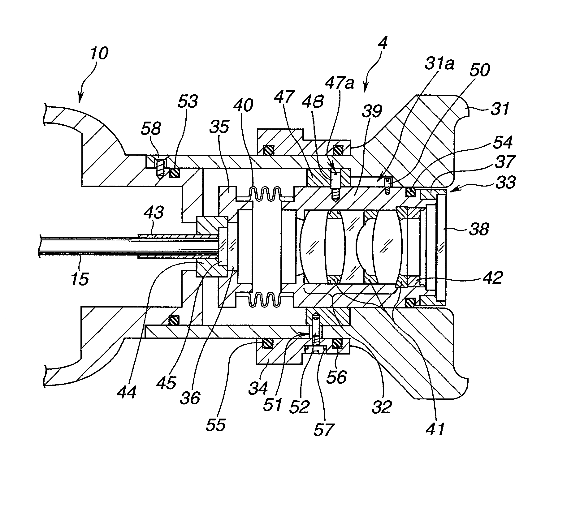
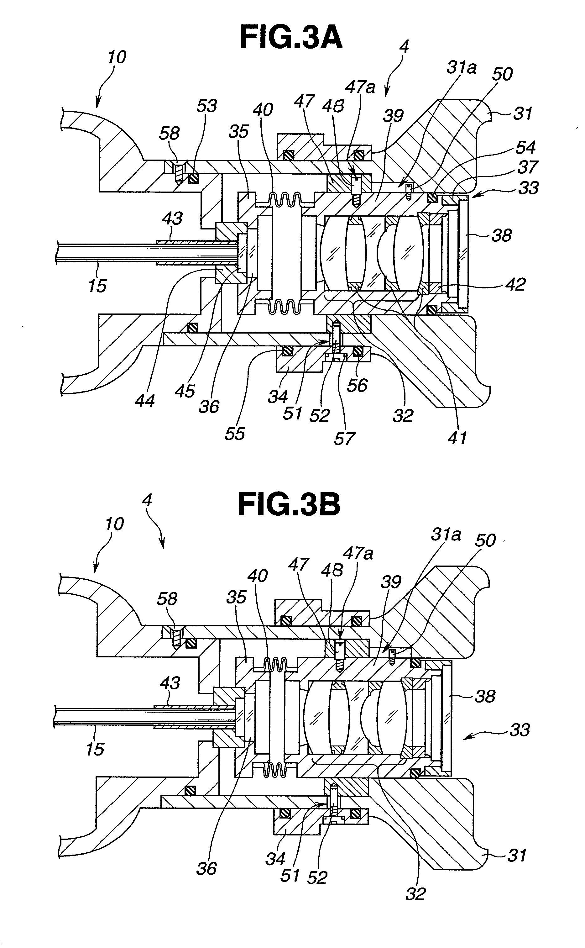
[0163] Various types of airtightly-sealed eyepiece lens units can be arranged by using the bellows having a changing diameter as a tubular hard airtight partition member.

[0164] Another arrangement of an eyepiece lens unit 33A constituting an eyepiece section 4B will be described with reference to FIG. 9 and FIG. 10.

[0165] The eyepiece lens unit 33A of the embodiment is provided with only one eyepiece lens 91 in place of an eyepiece lens group 32 disposed to an eyepiece lens frame 39. The eyepiece lens 91 is made from glass or sapphire whic...

second embodiment

[0183] the present invention will now be described with reference to FIGS. 12 and 13.

[0184] As shown in FIG. 12, an eyepiece section 4D of the embodiment has an eyepiece 102 integrally fixed to a main body 10. An eyepiece lens unit 103 having an eyepiece lens group 106 is disposed in the eyepiece 102.

[0185] The eyepiece lens unit 103 mainly comprises an outside frame 104 made of metal, a main body frame 105 made of metal, an eyepiece lens frame 107 made of metal, and a cover glass 108. The metal outside frame 104 is formed in an approximate pipe-shape and constitutes a shell; the metal main body frame 105 is formed to an approximate bobbin-shape, disposed to the internal peripheral surface of the outside frame 104, and has convex sections 105a and 105b formed at both sides thereof and an inner space 105C; the eyepiece lens frame 107 is disposed in the inner space 105c of the unit main body frame 105, formed as a pipe-shape and includes an eyepiece lens group 106 which is disposed in...

third embodiment

[0216] the present invention will now be described with reference to FIG. 16.

[0217] In an eyepiece section 4F of the embodiment, a visibility adjustment member mounting section 159 (hereinafter, referred to as the "member mounting section") is disposed in an image transmission light passage between an end of an image guide fiber 15 and an eyepiece lens unit 103B. The member mounting section 159 acts as an air-converted light passage length changing member mounting section into which a visibility adjustment member 150 is inserted. The visibility adjustment member 150 acts as an air-converted light passage length changing member for converting an air-converted light passage length. That is, the visibility adjustment member 150 acts as a focal position varying means. As described below, a plurality of different kinds of visibility adjustment members 150 are prepared. Note that numeral 156 denotes a rubber lid which is mounted on the member mounting section 159 after the visibility adju...


PUM


Abstract

An endoscope suitable for autoclave sterilization includes an insertion section having an objective lens section disposed at the extreme end thereof for focusing a subject image and an eyepiece section located on the base end side of the inserting section and including at least an eyepiece lens. an image guide fiber is disposed in the bundle for transmitting the subject image in an observation section focused by the objective lens section. An eyepiece lens unit is disposed in the eyepiece section, the eyepiece lens unit causing the eyepiece lens to confront the base end structure whose hermetic seal level is higher than the watertight seal level of the shell of the endoscope. A focus position changing means is disposed to the eyepiece lens unit to change the focus position of the eyepiece lens. The eyepiece section is so constructed and/or assembled that the autoclave sterilization process does not cause water vapor or the like to adversely affect the operability of the eyepiece section.

Description

RELATED APPLICATIONS[0001] This is a continuation of U.S. patent application Ser. No. 09 / 386,718, filed Aug. 31, 1999, entitled ENDOSCOPE SUITABLE FOR AUTOCLAVE STERILIZATION.BACKGROUND OF THE INVENTION[0002] 1. Field of the Invention[0003] The present invention relates to an endoscope with an image guide fiber suitable for autoclave sterilization whose observing capability is not deteriorated by a high pressure / high temperature water vapor when the endoscope is sterilized in an autoclave.[0004] 2. Description of the Related Art[0005] Conventionally, medical endoscopes are widely used to observe an internal organ in a cavity by inserting a slender insertion section into the cavity and to perform various kinds of medical treatments using medical instruments inserted through a medical instrument channel when necessary. Further, industrial endoscopes capable of observing and inspecting the flaw, corrosion and the like in the interior of boilers, turbines, engines, chemical plants and t...

Claims


Application Information

Patent Timeline
IPC IPC(8): A61B1/12A61L2/07G02B23/24
CPCA61B1/00188A61B1/00195A61B1/121A61L2/07G02B23/2423G02B23/2453G02B23/26
Inventor HIGUMA, MASAKAZUFUTATSUGI, YASUYUKINAKAMURA, ICHIROYOSHIMOTO, YOSUKISAITO, HIDETOSHIAONO, SUSUMUYAMAGUCHI, TAKAOTATSUNO, YUTAKAKISHI, TAKAHIROKURA, YASUHITONAKATSUCHI, KAZUTAKANAKAMURA, TAKEAKI
Owner OLYMPUS CORP
Why Eureka
Try Eureka