Method of measuring transcutaneous access blood flow

Inactive Publication Date: 2002-09-12
IN LINE DIAGNOSTICS CORP +1
View PDF0 Cites 23 Cited by
  • Summary
  • Abstract
  • Description
  • Claims
  • Application Information

AI Technical Summary

Benefits of technology

0011] It is therefore a primary object of the present invention to provide a straightforward metho...

Problems solved by technology

Because of the complicating factors associated with the tissue structure of the access site, most previous methods (with exception of color Doppler...

Method used


Image

  • Method of measuring transcutaneous access blood flow
  • Method of measuring transcutaneous access blood flow
  • Method of measuring transcutaneous access blood flow

Examples


first embodiment

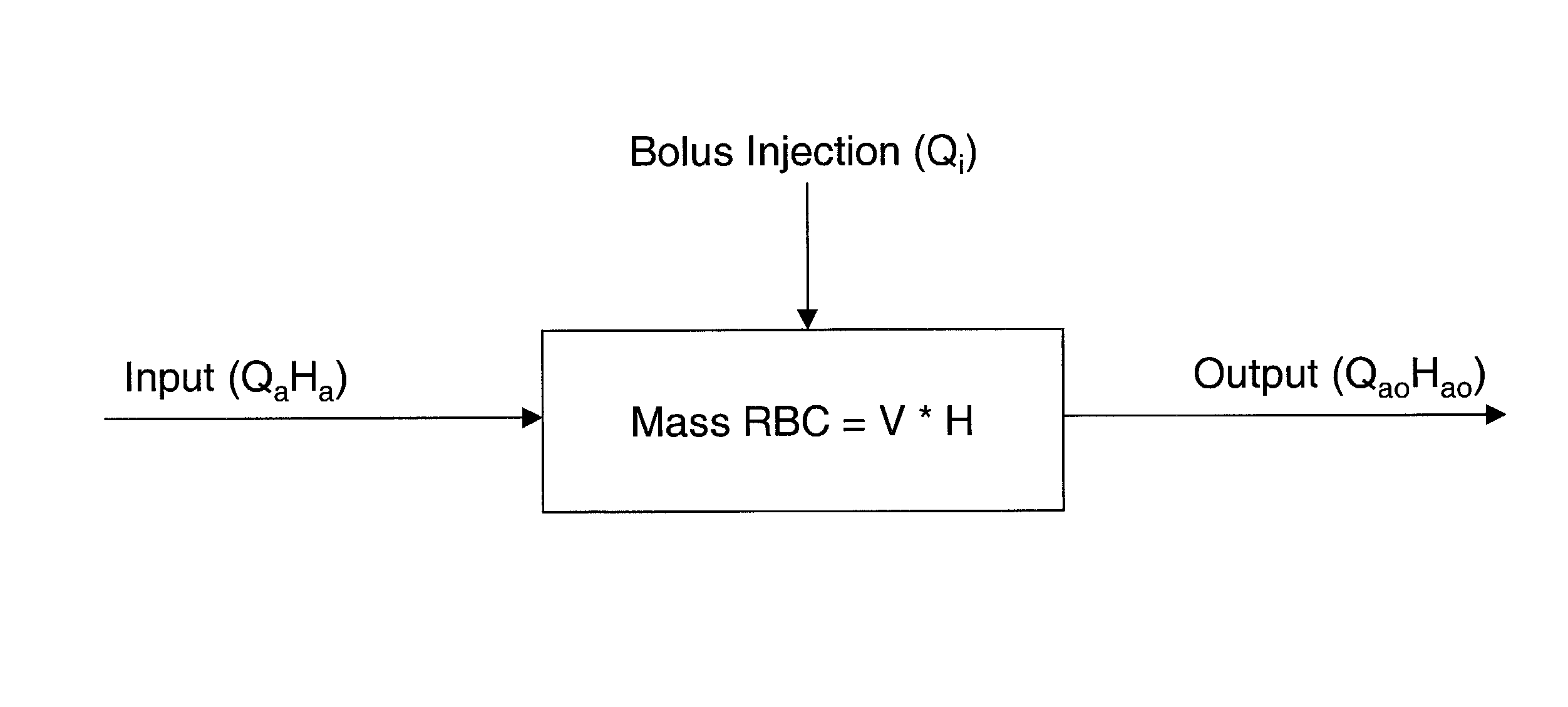
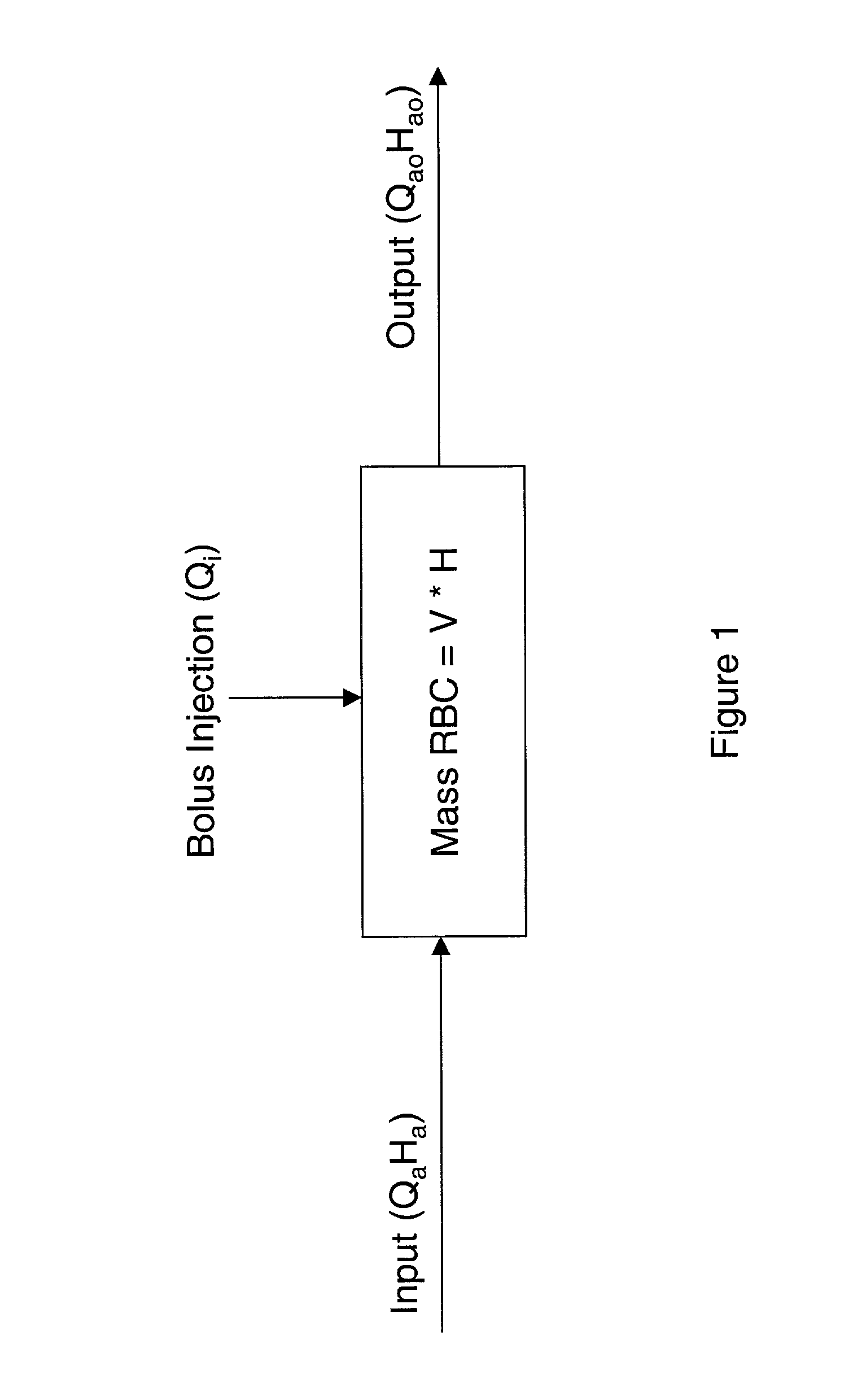
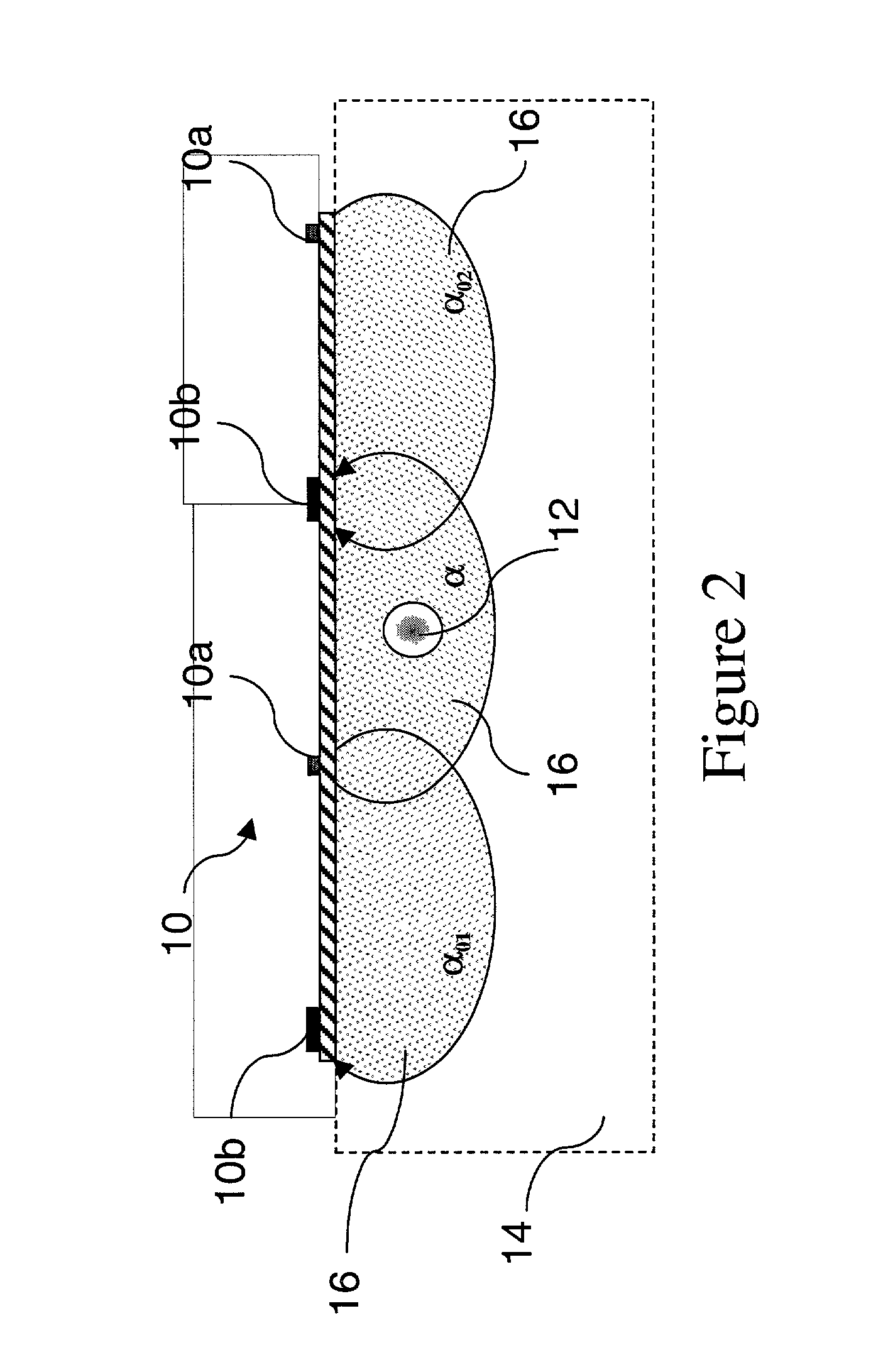
[0101] In the method, a stable (baseline) value H.sub.a proportional to the hematocrit in the access is first obtained. Then, a known volume (V) of a reference diluent (for example, normal saline) is injected into the dialysis venous line upstream of the venous needle. The diluent reduces the hematocrit in the vascular access site 12 beneath the sensor 10 to a time-dependent hematocrit H(t) during the injection. Using the signals produced from the time the diluent is injected to the time the signal returns to the baseline value, Q.sub.a can be calculated by the monitoring system using either the transient formulation (equation (9)) or the steady state formulation (equation (10)).

second embodiment

[0102] A method in accordance with the present invention is a method of measuring TQ.sub.a based on Q.sub.i.DELTA.T (the steady flow formulation, a transit time). The sensor may be of the type shown in FIGS. 2, 8, or 14 of the co-pending application.

[0103] The TQ.sub.a detector / emitter-set array is applied parallel to the flow and atop the access site 12 at H.sub.a0 between the venous needle site 12b and the access / vein connection 20c. The TQ.sub.a array emitters can be spaced at 8, 16, 20, and 24 mm for averaging Q.sub.a and better SNR. Saline injection is achieved via the drip bag 30c and the dialyzer pump 30b or via a syringe inserted into the arterial needle port 12a. Before dialysis begins and while the AV circuit is primed with saline, the arterial line in the hemodialysis circuit is clamped off, the saline drip bag 30c is opened, and two priming flushes of two seconds duration each are infused into the shunt flow at differing blood pump flow rates of Q.sub.i1 and Q.sub.i2, su...

third embodiment

[0110] A method in accordance with the present invention is a method of measuring TQ.sub.a in a hemodialysis circuit based on prime TQ.sub.a. In this embodiment, a hemodialysis circuit, the priming saline volume is used as a single 10 second saline bolus when Q.sub.b=300 ml / min. Preferably, the TQ.sub.a sensor is as shown in FIG. 20 of the co-pending application, is 24 mm square, and employs an outboard sensor array capable of making both parallel and perpendicular measurements. The TQ.sub.a sensor is applied over the H.sub.a0 shunt area, preferably between the venous needle site 12b and the access / vein connection 20c, as shown in FIG. 3 in connection with the sensor 10.

[0111] Prior to the priming dilution, the TQ.sub.a sensor makes a perpendicular measurement of .alpha. of normal shunt flow. The (arterial) dialyzer Q.sub.b pump 30b is then run for 10 seconds to clear the saline. As the saline enters and mixes with the shunt flow, the second TQ.sub.a sensor 10 makes perpendicular me...


PUM


Abstract

Indicator dilution techniques are used to measure vascular access flow rates during routine hemodialysis. A bolus injection port is used to infuse a specific volume (V.sub.i) of an indicator diluent, such as saline or dye, into the patient cardiovascular circuit by one of the following: 1. Needle injection of a known volume (bolus) of indicator diluent directly into the access site in the presence or absence of the hemodialysis circuit. 2. Infusion of an indicator diluent into the arterial, venous line upstream of the venous needle. 3. Turning the ultrafiltration of the dialysis delivery system from OFF to ON and OFF again over a predetermined time period. 4. In a hemodialysis circuit, turning on the hemodialysis pump and using the priming saline volume as a single saline bolus. A transdermal sensor is used to measure the percent change in a blood parameter. The sensor is positioned directly over the vascular access site a prescribed distance downstream of the injection site and upstream of the access-vein connection. The sensor employs emitter and detector elements at multiple spacings (d.sub.1, d.sub.2) for the purpose of measuring the bulk absorptivity (.alpha.) of the area immediately surrounding and including the access site, and the absorptivity (.alpha..sub.0) of the tissue itself.

Description

BACKGROUND OF THE INVENTION[0001] 1. Field of the Invention[0002] The present invention relates to a method for transcutaneously measuring access blood flow. More specifically, the invention relates to a method for measuring access blood flow through the optical measurement of percentage change in a blood parameter and application of the Ficke dilution principle.[0003] 2. Related Art[0004] Modern medical practice utilizes a number of procedures and indicators to assess a patient's condition especially in the dialysis setting. Hemodialysis is a process wherein an artificial kidney is required to function in the place of the patient's normal kidney in order to remove certain biologic waste products. When the human kidney no longer functions correctly removing waste products such as urea, potassium, and even excess water, blood must be removed from the patient via blood tubing lines and filtered through an artificial kidney or dialyzer. In this process blood is passed through the dialy...

Claims


Application Information

Patent Timeline
IPC IPC(8): G01F1/00A61B5/026A61B5/0275A61M1/14A61M1/36
CPCA61B5/0275A61M1/3653A61M1/3609A61M1/3656A61M1/3655A61B5/026
Inventor STEUER, ROBERT R.BELL, DAVID A.MILLER, DAVID R.
Owner IN LINE DIAGNOSTICS CORP
Why Eureka
Try Eureka